Description
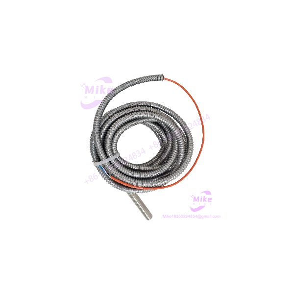
Emerson PR9376/010-011 | Hall Effect Speed Sensor
Dynamic Product Introduction
Detecting zero-speed rotation on heavy industrial turbines requires sensors that do not lose signal integrity when shafts crawl or stall under high thermal loads. Passive magnetic pickups often fail at low velocities because their output voltage depends entirely on target speed, leaving operators blind during startup or slow roll conditions. The Emerson EPRO PR9376/010-011 solves this limitation through active Hall-effect technology, delivering sharp digital pulse trains down to zero rotational speed regardless of how slowly the rotor turns.
Equipped with an integrated 5-meter stainless steel armored cable and open-end wire terminations, the PR9376/010-011 is engineered to handle harsh machine casing environments without signal degradation. The internal differential half-bridge sensor circuit actively compensates for electromagnetic noise and target gap variations, producing a clean push-pull square wave with a swift 1-microsecond rise time. Plant engineers rely on this unit to feed high-resolution speed and phase reference data directly into MMS 6000 protection racks.
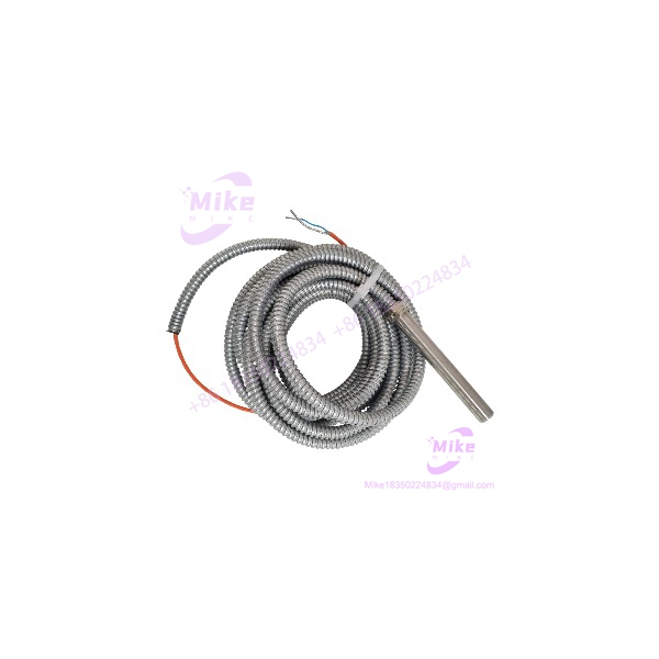
PR9376/010-011
Key Technical Specifications
- Sensing Principle: Differential Hall-effect sensor with internal signal amplification and DSP logic
- Output Signal Type: Push-pull square wave, 1 AC cycle per gear tooth or revolution
- Maximum Operating Frequency: 12 kHz (equivalent to 720,000 cycles per minute)
- Rise and Fall Time: Fast 1 µs response time
- Output Voltage Levels: High >10 V / Low <1 V (at 12 VDC with 100 kΩ load)
- Permissible Air Gap: 1.0 mm for Module 1 gears; 1.5 mm for Module ≥2 gears
- Target Material Requirements: Magnetically soft iron or structural steel (ST37); non-compatible with austenitic stainless steel
- Power Supply Requirements: 10 to 30 VDC at maximum 25 mA current draw
- Cable Configuration: 5-meter total length, PTFE core insulation protected by a flexible stainless steel armor hose, open-end wire termination
- Operating Temperature Range: -25°C to +100°C (-13°F to +212°F); storage down to -40°C
- Enclosure Ingress Protection: IP67 sealed stainless steel housing body
- Weight (Sensor Assembly): Approximately 410 grams including cable assembly
Global Sourcing & Live-Test SOP (Transparency Core)
Sourcing surplus or pre-owned turbine instrumentation demands rigorous verification before installation on critical assets. Every PR9376/010-011 unit entering inventory undergoes a strict multi-point validation protocol:
- Inbound Verification: Serial numbers on the stainless steel housing and cable tags are checked against factory distribution records. We inspect the 5-meter armored hose for twist fractures, check the PEEK/resin sensor tip for impact cracks, and verify stripped wire ends for oxidation.
- Live Simulation: The sensor head is mounted onto an automated test rig equipped with a reference ST37 steel toothed wheel driven by a variable-speed motor. The open wire leads connect directly to an authentic MMS 6000 speed monitoring card powered by a regulated 24 VDC bench supply.
- Diagnostics: The test rig cycles the target gear from zero-speed creep up to the 12 kHz frequency limit. An oscilloscope captures square-wave output voltages to verify that rise times remain under 1 µs and high/low logic levels meet the >10 V / <1 V threshold requirements.
- Electrical & Insulation Soak: Insulation resistance testing is performed by applying 500 VDC between the internal PTFE conductors and the outer stainless armor sheath, requiring a clean reading exceeding 100 MΩ.
- Final Prep: Calibration data sheets are logged, bare wire ends are fitted with protective heat-shrink sleeves, and the PR9376/010-011 unit is sealed inside an anti-static moisture-barrier bag.
The Field Engineer’s Pitfall Guide
❗ Installing Over Austenitic Stainless Steel Target Wheels: Never pair the PR9376/010-011 with stainless steel target gears (such as 304 or 316 grades). Hall-effect sensors rely on magnetic soft iron or carbon steel (like ST37) to distort the internal magnetic bias field. Using austenitic stainless steel targets prevents proper flux variation, resulting in a flatline output with zero pulse generation.
❗ Exceeding Air Gap Tolerances on High-Expansion Rotors: Thermal growth on large steam turbines can alter radial clearances significantly. If the mechanical air gap exceeds 1.5 mm for larger gear modules during full load operation, the magnetic field distortion weakens past the internal switching threshold—an oversight that causes intermittent dropouts during high-temperature runs.
❗ Improper Shield Grounding and Induced Electrical Noise: The PR9376/010-011 includes an integrated armor shield and internal drain wiring. In field deployments, letting the armor jacket touch multiple grounded metal structures or failing to ground the shield exclusively at the monitor rack cabinet creates ground loops that inject high-frequency electrical noise into your speed pulse train.
Intent-Driven FAQ
Q: Can the PR9376/010-011 detect rotational speed at zero RPM or standstill? Yes. Unlike passive magnetic pickups that require target motion to induce voltage, the active Hall-effect design of the PR9376/010-011 detects static magnetic target presence. This allows reliable zero-speed detection, barring gear monitoring, and low-speed standstill tracking.
Q: How does the PR9376/010-011 differ from standard non-armored sensor models? The designation indicates specific physical build options. The /010 suffix specifies an integrated stainless steel protective armor hose over the PTFE cable, and the -011 code designates a 5-meter length with open-end wire terminations for direct terminal block wiring.
Q: Can I shorten or splice the 5-meter armored cable in the field? Splicing or shortening the cable alters total loop capacitance and resistance parameters. While digital pulse signals are more resilient than analog carrier loops, altering factory cable lengths on certified machinery wiring loops is strongly discouraged to maintain compliance with installation standards.
Q: What monitoring cards are compatible with this sensor? The PR9376/010-011 is engineered specifically for integration with Emerson EPRO MMS 6000 series turbine supervisory instrumentation cards, such as the MMS 6312 dual-channel speed monitor, which processes the push-pull square-wave pulses for overspeed protection.
Q: How do I test the internal circuit health of the sensor during an outage? Disconnect the sensor leads from the terminal block. Use a digital multimeter to check continuity and supply voltage drop across the power and ground pins (should draw under 25 mA at 10–30 VDC). You can also monitor the signal output pin with an oscilloscope while manually passing a piece of ferrous metal across the sensor tip to verify pulse switching.