


Description
CCC FAN-10-2 | Vanguard Series 5 Fan Tray Assembly
Product Introduction
Thermal management is not an accessory on a compressor controller. If airflow through a populated chassis drops, CPU cards, I/O processors, power supplies, and communication hardware can all be pushed toward temperature limits before a process engineer sees an obvious control-system fault.
The CCC FAN-10-2 is the dedicated fan tray assembly documented for the Vanguard Series 5 CPCI-10-D2 duplex chassis. CCC’s DS5109 documentation specifies six 3.62-inch (92 mm) fans, with each fan rated at approximately 60 CFM. The assembly uses ABEC 3 double-shielded chrome ball bearings and carries a documented fan MTBF of 60,000 hours.
This distinction matters during replacement sourcing. FAN-10-2 is not a controller CPU, I/O processor, or generic “fan module.” It is a complete chassis cooling assembly intended for the 10-slot duplex Vanguard Series 5 architecture. Independent CCC parts listings also identify it as the CPCI-10-D2 fan tray assembly.
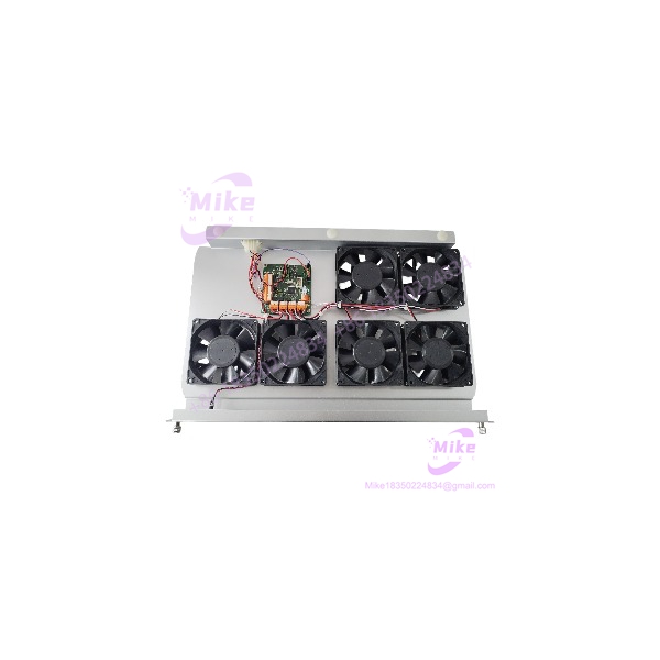
FAN-10-2
Key Technical Specifications
- Manufacturer: Compressor Controls Corporation (CCC)
- Part Number: FAN-10-2
- System: Vanguard Series 5
- Application: CPCI-10-D2 duplex chassis
- Assembly Type: Fan tray assembly
- Number of Fans: 6
- Individual Fan Diameter: 3.62 in. / 92 mm
- Airflow: 60 CFM per fan
- Bearing Construction: ABEC 3, double-shielded chrome ball bearing
- Fan MTBF: 60,000 hours
- Fan Tray Width: 16.5 in.
- Fan Tray Height: 1.5 in.
- Fan Tray Depth: 10.25 in.
- Metric Dimensions: Approximately 419 × 38 × 261 mm
- Associated Chassis: CPCI-10-D2-NPS
- Chassis Application: Vanguard Series 5 duplex controller architecture
The six-fan configuration and mechanical envelope are specifically documented in CCC’s DS5109 specification. This is preferable to unsupported reseller claims about fan voltage, RPM, PWM control, hot-swapping, temperature sensors, or onboard intelligence.
Cooling Architecture and System Role
The FAN-10-2 occupies the cooling position associated with the 10-slot duplex chassis.
The relevant Vanguard architecture uses a CPCI chassis containing redundant processing and I/O hardware. The chassis specification identifies four PSMU-350 power supplies, two MPU cards, and three pairs of I/O cards in the duplex configuration. That hardware density makes continuous forced-air cooling part of the system’s normal thermal-management strategy.
The FAN-10-2 provides six individual airflow sources rather than functioning as an electronic controller. Each fan is specified at 60 CFM, giving a nominal aggregate fan rating of 360 CFM before accounting for chassis restrictions, filters, pressure drop, and the actual operating point of the fans.
Do not interpret 360 CFM as guaranteed chassis airflow. It is simply the arithmetic sum of the documented individual fan ratings.
For a replacement unit, the mechanical interface and fan-tray arrangement are therefore just as important as the individual fan specifications.
Global Sourcing & Live-Test SOP
Inbound Verification
For a surplus or replacement , begin with physical identification.
Recommended inspection points:
- Confirm the marking.
- Photograph the complete assembly before unpacking.
- Verify the tray dimensions against the CPCI-10-D2 installation.
- Count all six fan positions.
- Inspect fan guards and mounting hardware.
- Check fan housings for cracking or deformation.
- Inspect connectors and wiring for heat damage.
- Check for excessive dust accumulation.
- Record serial or assembly identification where available.
For procurement records, retain photographs of the nameplate and assembly because visually similar fan trays exist for other Vanguard and legacy CCC chassis.
Mechanical Installation Check
Before energization:
- Confirm that the tray fits the intended 10-slot chassis.
- Verify mounting alignment.
- Check that no fan blade contacts its housing.
- Confirm free rotation of each fan.
- Inspect the airflow path for blocked filters or debris.
- Verify that installed cards do not obstruct the cooling path.
A fan that spins freely by hand is not necessarily a healthy fan. Bearing noise, excessive axial/radial play, and startup behavior still need to be evaluated.
Live Functional Test
A recommended test-rack procedure includes:
- Install the in a compatible CPCI-10-D2 chassis.
- Energize the chassis using the correct system power architecture.
- Verify startup of all six fans.
- Listen for abnormal bearing noise.
- Check for vibration or mechanical imbalance.
- Verify stable operation after thermal stabilization.
- Measure airflow or differential pressure where appropriate.
- Monitor fan behavior during a representative controller load.
- Record abnormal fan startup, intermittent stopping, or excessive noise.
The purpose of the test is not simply to prove that the motors rotate. The objective is to establish that the cooling assembly can provide stable airflow to a populated chassis under realistic operating conditions.
Final QC Preparation
After testing:
- Clean the fan intake and exhaust surfaces.
- Protect connectors against contamination.
- Record the test date and chassis used.
- Record the number of functioning fans.
- Package the tray against impact and vibration.
- Use ESD precautions around adjacent controller electronics.
- Preserve the original part-number marking.
For a safety- or availability-critical compressor control system, keep the test record with the spare-parts traceability documentation.
Field Engineer’s Pitfall Guide
❗ Do not substitute a generic fan tray based only on physical dimensions.
The is specifically associated with the Vanguard Series 5 10-slot duplex chassis. The electrical interface, mounting arrangement, airflow direction, and chassis pressure characteristics all matter. A visually similar fan assembly can produce insufficient cooling even when it physically fits.
❗ Do not assume the six fans provide a guaranteed 360 CFM through the chassis.
CCC specifies 60 CFM per fan, but airflow ratings are individual fan specifications. Actual system airflow depends on chassis resistance, filters, card density, and operating conditions. Treat 360 CFM as a nominal aggregate fan rating—not a measured chassis airflow figure.
❗ Do not accept a used tray solely because all six fans start.
A fan with degraded bearings can start normally and still produce excessive vibration, noise, or reduced airflow. For a compressor-control cabinet expected to operate continuously, bearing condition and thermal performance deserve a proper run test.
Intent-Driven FAQ
Q1. What is the CCC ?
The is a fan tray assembly used with the Compressor Controls Corporation Vanguard Series 5 10-slot duplex chassis. CCC documentation identifies the assembly with the architecture.
Q2. How many fans are installed in the ?
The documented assembly contains six 3.62-inch (92 mm) fans. Each fan is rated at approximately 60 CFM.
Q3. What is the MTBF?
CCC’s documented specification gives a 60,000-hour MTBF for the fan. This should be treated as a component reliability specification rather than a guarantee of remaining life for a used assembly.
Q4. What chassis does the fit?
The is documented for the 10-slot duplex chassis used in the Vanguard Series 5 system. Independent CCC parts listings also identify it as the fan tray assembly.
Q5. Is a controller or I/O module?
No. It is a mechanical cooling assembly. It does not perform compressor-control logic execution, analog I/O processing, or communication processing.





