

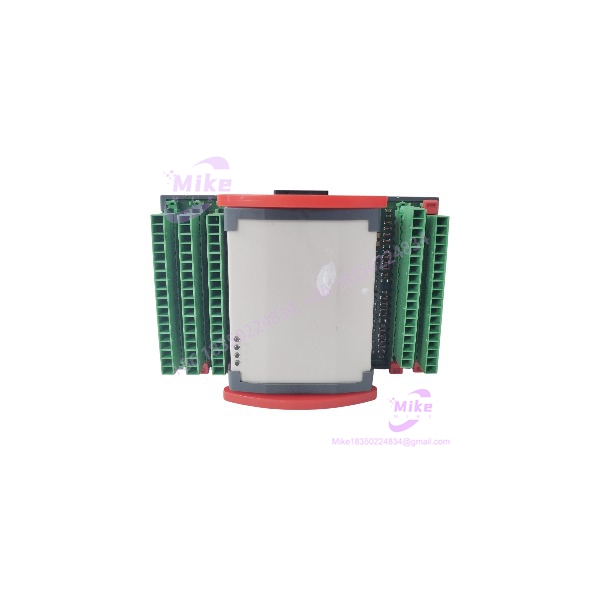
Description
Berghof QAIO164-V | 16 DI 4 AO Precision Voltage Hybrid Module
Dynamic Product Introduction
Field engineers managing Berghof-driven automated processing cells know how crucial precise voltage reference signals are for variable frequency drives (VFDs) and proportional valves. When an analog voltage channel drifts or a digital sensor bank loses optocoupler isolation, replacing the failing module without altering backplane routing or control code becomes a critical priority.
The Berghof QAIO164-V combines high-density digital monitoring with dedicated analog voltage generation inside a compact expansion housing. Featuring 16 optocoupler-isolated 24 V DC digital inputs alongside 4 high-resolution analog voltage outputs (0–10 V / ±10 V), the QAIO164-V (“V” designation specifically highlighting voltage-mode output circuitry) delivers clean, noise-immune reference signals. Operating seamlessly across standard industrial fieldbus protocols such as Modbus and Profibus, the QAIO164-V provides the exact signal conversion parameters required for servo drive speed commands, actuator positioning, and multi-sensor machine automation.
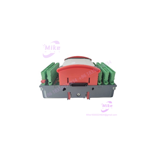
QAIO164-V
Key Technical Specifications
- Digital Inputs: 16 channels (24 V DC, sink/source compatible)
- Analog Outputs: 4 channels dedicated to voltage mode (0–10 V DC or ±10 V DC)
- Nominal Operating Voltage: 24 V DC (±15% voltage tolerance)
- Digital Input Isolation: Galvanic optical isolation per channel group
- Analog Resolution: 12-bit / 16-bit DAC conversion
- Analog Output Load Impedance: Minimum 1 kΩ load resistance
- Communication Protocols: Modbus-RTU, Profibus-DP slave capability
- Status Indicators: Channel-specific LED diagnostics for all digital inputs
- Wiring Interface: Removable screw-terminal connector blocks
- Mounting: Standard 35 mm DIN rail mounting
Global Sourcing & Live-Test SOP (Transparency Core)
Sourcing surplus or legacy automation components requires complete functional validation to ensure sub-millivolt output accuracy and robust noise suppression.
Inbound Verification & Traceability
- Paperwork Audit: Verification of serial numbers against OEM production logs to confirm exact hardware revision and voltage-variant manufacturing batch.
- Physical Inspection: Comprehensive examination of terminal pins, backplane connectors, housing latch mechanics, and internal PCB traces.
Live Rack Simulation & Diagnostics
- Power Rail & Bus Handshake: Module is mounted onto a Berghof test rack to verify 24 V DC startup and fieldbus network address recognition.
- 24 V DC Digital I/O Test: Driving high-speed voltage pulses across all 16 digital input channels while validating LED indicator response and isolation barrier performance.
- Precision Voltage Output Calibration: Sweeping full-scale voltage steps (0 to +10 V DC / -10 to +10 V DC) on all 4 analog output channels while measuring linearity and noise floor using a calibrated Fluke 8846A precision multimeter.
- 24-Hour Stress Run: Module undergoes a continuous 24-hour thermal chamber test under full continuous output loads to guarantee zero thermal drift and output amplifier stability.
Final Prep
- EEPROM Verification: Confirming onboard configuration parameters and factory default states.
- ESD Safe Packaging: Sealed in anti-static shielding bags with moisture desiccant packs before double-boxed air shipment.
The Field Engineer’s Pitfall Guide
- ❗ Model Variant Confusion (QAIO164-A vs. QAIO164-V): The “A” variant generally supports selectable current/voltage outputs, whereas the “V” variant features dedicated voltage output drivers optimized for low-impedance voltage loops. Installing a QAIO164-V in a loop expecting a 4–20 mA current drive will result in total signal breakdown and drive fault errors.
- ❗ Analog Voltage Output Loading Limits: Exceeding the maximum drive current or loading the voltage outputs with an impedance lower than 1 kΩ will trigger internal short-circuit limiting in the DAC output drivers, leading to voltage drops and position tracking errors.
- ❗ Fieldbus Node Address & Baud Rate Switch Settings: When replacing a failed QAIO164-V, ensure DIP switch configurations for fieldbus node addressing and baud rate settings are matched exactly to the original unit before applying power.
Intent-Driven FAQ
What is the main difference between the QAIO164-A and QAIO164-V modules?
The QAIO164-V is specifically optimized for dedicated precision voltage outputs (such as 0–10 V DC or ±10 V DC), whereas the QAIO164-A model is configured for general analog current (4–20 mA) and mixed analog output loops.
Will replacing a QAIO164-V require modifying the PLC program?
No. Hardware replacement is completely transparent to the host controller as long as the replacement unit uses the same fieldbus address, baud rate, and terminal pin layout as the original card.
Is the QAIO164-V hot-swappable during live system operation?
No. Standard Berghof expansion cards are not hot-swappable. Always disconnect main 24 V DC system power before inserting or removing the QAIO164-V module to avoid electrical arcing or system bus faults.
What terminal connector type is used on the QAIO164-V?
The module utilizes detachable screw-terminal connector blocks, allowing quick replacement without desoldering or re-wiring individual field conductors.
What warranty coverage is provided with replacement hardware?
All verified QAIO164-V modules include a standard 12-month full-replacement warranty covering internal hardware functionality, input signal acquisition, and analog voltage output performance.
If you need help checking terminal wiring pinouts or verifying fieldbus address settings for your QAIO164-V installation, let me know your system details and I can assist with the setup.





