

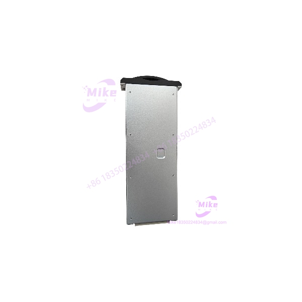
Description
SIS PW01 | Safety Instrument System Power Supply Controller
Dynamic Product Introduction
Power sags or unregulated noise on primary power rails can instantly compromise Safety Instrumented Systems (SIS), causing false trips or, far worse, preventing an emergency shutdown (ESD) sequence from executing on active process plants. Standard commercial power modules lack the diagnostic loop monitoring and isolation required to meet strict Functional Safety standards across high-risk petrochemical, power generation, and chemical process cells. The GE Fanuc SIS PW01 module serves as a dedicated high-integrity power supply and system logic controller interface built specifically for industrial safety architecture.
Designed to accept a 24 VDC nominal feed, the SIS PW01 provides regulated, isolated DC rails to power local safety processor racks and digital/analog I/O cards. (Honestly, having clean, uninterruptible power distribution inside an ESD rack prevents spurious process trips that can freeze production lines for days.) With integrated dual-port 10/100 Mbps Ethernet pathways and high-speed status reporting, the SIS PW01 delivers real-time health diagnostics directly to supervisory platforms—though maintaining long-term reliability relies on keeping power feed ripples within strict threshold limits.
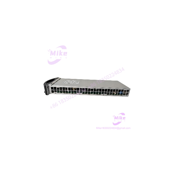
PW01
Key Technical Specifications
- Manufacturer & System Platform: GE Fanuc / GE Mark VI / SIS Safety Series Architecture
- Module Model Designation: SIS PW01 / SIS-PW01
- Primary Function: Safety system power distribution and backplane logic supply
- Input Supply Voltage: 24 VDC nominal (20.4 to 28.8 VDC operational range)
- Output Power Rails: Regulated internal backplane logic voltages and field loop auxiliary power
- Communication Interfaces: Dual 10/100 Mbps RJ45 Ethernet ports supporting Modbus TCP/IP protocols
- Redundancy Support: Active dual-redundant power rail sharing and fault reporting
- Diagnostic Capabilities: Integrated power rail monitoring, line fault sensing, and front-panel LED indicators
- Operating Ambient Temperature: 0°C to +60°C (32°F to 140°F) continuous operational range
- Enclosure Protection Rating: IP20 rated heavy industrial protective chassis
Global Sourcing & Live-Test SOP (Transparency Core)
Sourcing pre-owned or secondary-market safety system hardware demands exhaustive electrical testing before installing modules into active trip circuits. Every GE Fanuc SIS PW01 unit entering inventory undergoes a detailed five-stage bench qualification process:
- Inbound Verification: Serial numbers, PCB silk-screen layers, and component revision codes are checked against OEM manifests. We inspect backplane multi-pin connectors for bent terminals, examine electrolytic capacitors for thermal fatigue, and check terminal blocks for mechanical wear.
- Live Simulation: The SIS PW01 module is installed into an authentic SIS rack backplane connected to an adjustable 24 VDC bench power supply.
- Diagnostics & Output Regulation: Electronic loads are applied across all internal output rails. Using a Fluke 87V digital multimeter and an oscilloscope, we verify that output voltage regulation holds within ±1.5% and peak-to-peak AC ripple remains under strict factory millivolt limits under 100% load conditions.
- Communication & Redundancy Test: Ethernet ports are linked to a network test suite to verify Modbus TCP/IP handshakes, data packet transmission, and seamless dual-port switchover.
- Final Prep: Non-volatile memory configuration registers are reset, terminal connections are cleaned, and the SIS PW01 module is vacuum-sealed in conductive anti-static moisture-barrier packaging.
The Field Engineer’s Pitfall Guide
❗ Overloading the Auxiliary 24V Field Output Bus: While the SIS PW01 provides power for local backplane logic, tapping its auxiliary outputs to drive high-draw external field devices (such as large solenoid valves or heavy motor starters) can exceed the internal current limits. Exceeding rated amperage limits trips the module’s foldback current protection, causing unexpected safety rack drops and emergency trips.
❗ Operating Without Proper Protective Grounding: Connecting the 24 VDC supply lines to the SIS PW01 without establishing a low-impedance protective earth (PE) ground bond invites high-frequency electrical noise onto the safety backplane. In field deployments, floating ground connections lead to corrupted I/O channel communication and spurious system fault alarms.
❗ Hot-Swapping Under Live AC/DC Line Feeds Without Bypass: While safety system racks are engineered for high availability, removing the SIS PW01 without verifying that a secondary redundant power module is actively supplying the bus will instantly shut down the safety rack. Always confirm that redundant power rails are active before pulling the module.
Intent-Driven FAQ
Q: What is the primary role of the SIS PW01 module within a safety instrumented system? The SIS PW01 functions as both a power supply and a system communications/diagnostic node. It steps down and regulates incoming power for internal backplane logic cards while monitoring rail health and transmitting diagnostic status to supervisory control networks.
Q: Does the SIS PW01 require software configuration before deployment? Basic power distribution is hardware-based, but configuring network communication protocols (e.g., Modbus TCP/IP settings and IP addresses) requires establishing a connection via the Ethernet configuration software tool.
Q: What do the front-panel status LEDs indicate on the SIS PW01? The status LEDs provide real-time hardware indications: Power OK (solid green indicates healthy DC input/output levels), Active/Fault (blinking or red indicates logic fault or rail overload), and Link/Act (indicates Ethernet network traffic on the communication ports).
Q: Can the SIS PW01 be used in non-GE system racks? No. The mechanical form factor, backplane bus pinout, and keying structures are specifically engineered for compatibility with GE SIS / Safety Instrumented System backplane architectures.
Q: What should I check first if the SIS PW01 displays a power fault LED? First, measure the incoming primary DC supply voltage at the terminal block to ensure it falls within the 20.4 to 28.8 VDC operational window. Next, calculate the combined power draw of all installed rack modules to confirm total current limits have not been exceeded.





