

Description
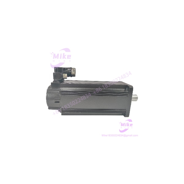
Bosch Rexroth MSK071D-0450-NN-M1-UP1-NNNN | IndraDyn S Motor Key Spec, New In Stock
Architect’s Product Breakdown
The MSK071D-0450-NN-M1-UP1-NNNN servo motor acts as an extended-length, high-capacity rotary actuator engineered for demanding multi-axis motion systems. Driven by Bosch Rexroth IndraDrive controllers, this 071-frame D-stack variant provides expanded thermal mass and higher torque ratings than shorter C-stack models, making it ideal for heavy high-inertia loads in automated metal-forming machinery, heavy material handling, and large gantry axes. Its integrated, electrically released holding brake provides fail-safe positional locking during power-down cycles on vertical or gravity-loaded mechanisms.
Integrating this unit into existing machinery requires verifying drive firmware compatibility and ensuring that the IndraDrive power supply module can handle the inrush current of the integrated holding brake circuit. The rotatable 240-degree connector layout simplifies cabinet integration and relieves mechanical stress on heavy power and feedback cable assemblies.
Engineering teams must ensure proper thermal dissipation and rigorous shield bonding. Because the motor relies on natural convection cooling, enclosing it in tightly sealed housings without adequate ambient airflow can cause thermal derating under heavy cyclic loads.
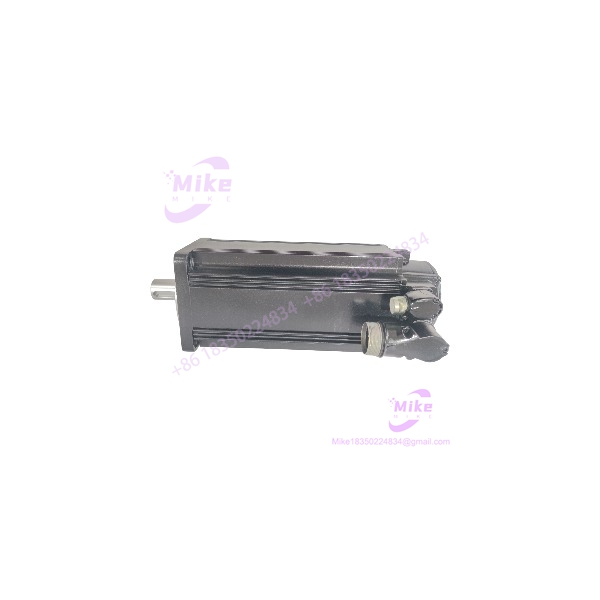
MSK071D-0450-NN-M1-UP1-NNNN
Key Technical Specifications
| Parameter | Specification |
| Manufacturer | Bosch Rexroth (Indramat) |
| Model Number | MSK071D-0450-NN-M1-UP1-NNNN |
| Motor Family | MSK IndraDyn S Synchronous Servo Motor |
| Frame Size / Length | Size 071, Length D |
| Winding Code | 0450 |
| Cooling Type | Natural convection (Self-cooling) |
| Feedback Type | Optical multi-turn absolute encoder (Hiperface) |
| Shaft Design | Shaft with keyway and sealing ring (UP1) |
| Holding Brake | Integrated, electrically released holding brake |
| Protection Category | IP65 |
Field Engineer’s Pitfall Guide
- Premature Brake Release Failure: Attempting to rotate or back-drive the motor shaft while the holding brake is unpowered will cause severe friction wear on internal brake discs. Always verify that 24V DC brake release voltage is actively applied before commanding axis movement.
- Feedback Connector Pin Damage: Forcing the rotatable circular connector past its 240-degree mechanical stop or misaligning the internal keyway will bend delicate pins, resulting in immediate absolute encoder communication faults on the IndraDrive.
- Unshielded Cable Installations: Failing to clamp the motor power cable shield 360 degrees to the drive chassis ground introduces high-frequency electromagnetic noise, disrupting nearby sensitive feedback signals and analog loops.
QA & Testing SOP
- Visual & Origin Inspection: Verify factory seals, inspect housing coatings, check the keyed shaft for surface imperfections, and ensure connector pins are clean and straight.
- Live Test Environment: Couple the motor to a certified IndraDrive test stand to verify smooth commutation, holding brake engagement/release timing, and velocity tracking under load.
- Diagnostics & Handshake Tests: Execute encoder initialization routines, check multi-turn position register integrity, and perform a megohmmeter insulation resistance test on the motor windings.
- Preservation & Packaging: Install protective plastic caps over the shaft and connectors, wrap the unit in anti-static shielding material, and secure it inside heavy-duty industrial foam packaging.
Technical FAQ
Does the MSK071D-0450-NN-M1-UP1-NNNN require a battery backup for absolute positioning?
No. The multi-turn absolute optical encoder tracks position mechanically or via non-volatile storage integration, maintaining absolute position data across power losses without external backup batteries.
Can I operate this motor without connecting the holding brake wires?
No. If the holding brake is not supplied with the correct release voltage, it will remain permanently engaged and mechanically locked, leading to excessive current draw and immediate drive fault trips.
What is the function of the “UP1” design code in the model string?
The “U” indicates a rotatable connector housing, “P” specifies a shaft with a keyway and shaft sealing ring, and “1” indicates the inclusion of an integrated holding brake.
What software tool is used to configure and tune this servo motor?
Drive configuration, parameterization, and gain tuning are performed using the standard Bosch Rexroth IndraWorks engineering software platform.





