

Description
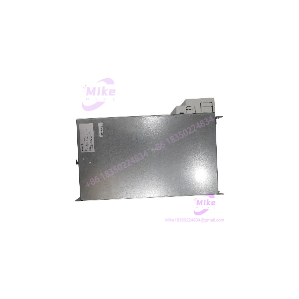
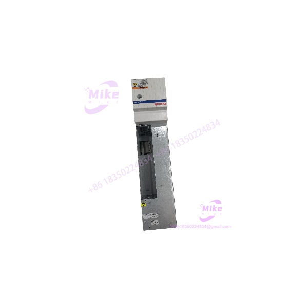
Bosch Rexroth HMS01.1N-W0070-A-07-NNNN | Single-Axis Inverter
Dynamic Product Introduction
The HMS01.1N-W0070-A-07-NNNN is not a conventional standalone AC-input VFD. It is a modular IndraDrive M single-axis inverter power section that takes energy from a high-voltage DC bus and produces controlled three-phase AC for a motor. In the original IndraDrive architecture, that DC bus can be supplied by compatible Rexroth supply units or converter stages rather than by feeding mains directly into the HMS power section.
The electrical numbers explain where this module belongs: 254–750 VDC input, 700 VDC nominal bus, up to roughly 70 A peak/current-class rating, and 42.4 A continuous output current. Published data also specifies 0–500 VAC output and maximum output frequency dependent on switching frequency, reaching 400 Hz at 4 kHz switching, 800 Hz at 8 kHz, 1,200 Hz at 12 kHz, and 1,600 Hz at 16 kHz. Those figures should be treated as drive-system limits rather than a promise that every motor/application can operate at those frequencies.
For a replacement project, the important point is architectural compatibility. This is a power module inside a larger IndraDrive system, so the matching control unit, motor feedback, firmware, DC-bus supply, motor data, and application configuration all matter. Swapping the housing because the current rating appears similar is not an adequate migration strategy.
HMS01.1N-W0070-A-07-NNNN
Key Technical Specifications
- Manufacturer: Bosch Rexroth / Indramat
- Series: IndraDrive M, HMS01
- Model: HMS01.1N-W0070-A-07-NNNN
- Material Number: R911295326
- Drive Type: Single-axis inverter power section
- Nominal DC-Bus Voltage: 700 VDC
- DC Input Voltage: 254–750 VDC
- Maximum Current: approximately 70 A
- Continuous Current: 42.4 A
- Output Voltage: 0–500 VAC
- Maximum Output Frequency: dependent on switching frequency; published values extend to 1,600 Hz at 16 kHz switching
- Cooling: Internal air cooling with integrated blower
- Protection Rating: IP20
- Typical Motor Rating: approximately 22 kW, application-dependent
- EMC Environment: EN 61800-3
- Dimensions: approximately 100 × 440 × 309 mm (W × H × D)
- Weight: approximately 9.4 kg in current catalog listings
The original Rexroth dimensional documentation gives additional mounting geometry and clearance requirements. The drawing shows a 440 mm main body dimension, 100 mm width, approximately 309 mm depth, and specified minimum clearance zones around the assembly. Motor-cable routing and the HAS02.1 accessory can affect the actual installation envelope.
Global Sourcing & Live-Test SOP
For a used, surplus, or refurbished HMS01.1N-W0070-A-07-NNNN, treat identification as a technical inspection rather than a visual match.
1. Inbound Verification
- Photograph the complete nameplate before removing packaging.
- Confirm HMS01.1N-W0070-A-07-NNNN and R911295326 against the purchase record.
- Record serial number, hardware revision, firmware information, and any visible configuration labels.
- Inspect terminal blocks, DC-bus connections, motor-output terminals, mounting points, and blower assembly.
- Check for evidence of DC-bus arcing, overheated terminals, cracked insulation, contamination, or unauthorized board repairs.
- Trace OEM paperwork where available; retain serial-number and configuration records for the procurement file.
- Do not substitute an .1N-W0054 or .1N-W0150 simply because it fits the same mechanical family.
2. Live Simulation
- Verify the test setup uses an appropriate compatible Rexroth DC-bus supply.
- Confirm DC-bus voltage before enabling the power section.
- Check precharge and bus behavior rather than applying full bus voltage blindly.
- Connect the correct control hardware and a known-compatible motor/feedback combination.
- Verify motor phase balance and feedback recognition before commanding rotation.
- Confirm enable, inhibit, fault reset, and emergency-stop behavior.
3. Diagnostic Testing
- Review drive fault memory and diagnostic messages.
- Verify encoder feedback and motor identification.
- Monitor DC-bus voltage during acceleration and deceleration.
- Check phase-current behavior under controlled load.
- Inspect blower operation and thermal behavior.
- Use a calibrated Fluke multimeter or equivalent CAT-rated instrument for static electrical verification; use appropriate high-voltage measurement equipment for energized DC-bus testing.
4. 24-Hour Heat Run
A replacement power section should not go directly from a cold bench into a production machine.
Run a controlled load cycle long enough to expose thermal instability, blower problems, intermittent feedback faults, and DC-bus abnormalities. Record temperatures, current, bus voltage, fault status, and motor behavior.
5. Final Preparation
Before shipment:
- Record exact hardware and firmware information.
- Record the tested control-unit combination.
- Preserve customer configuration data separately from the hardware.
- Photograph terminal condition.
- Seal the assembly in ESD-safe packaging.
- Use moisture protection for international shipment where appropriate.
- Clearly label the package as industrial electronic equipment with high-voltage DC-bus circuitry.
Field Engineer’s Pitfall Guide
❗ 1. Do not treat the 700 VDC bus like a normal 400/480 VAC drive
The .1N-W0070-A-07-NNNN is supplied from a high-voltage DC bus. Its published input range is 254–750 VDC, with 700 VDC nominal. That means bus isolation, discharge time, protective devices, insulation, and service procedures have to be handled accordingly. The power section is not simply a 480 VAC line-input inverter.
❗ 2. Firmware and control hardware can make an electrically correct replacement fail
The power section operates as part of an IndraDrive system. Control-unit type, firmware, motor data, encoder configuration, and application parameters must be checked together. A physically identical replacement can still generate configuration or communication faults if the surrounding drive system does not match.
Do not overwrite an existing machine configuration until the original parameters and firmware information have been preserved.
❗ 3. Leave room for cooling and motor-cable routing
IP20 does not mean the drive can be installed openly in a dirty industrial environment. The enclosure must provide appropriate environmental protection, and the integrated blower requires adequate airflow and clearance. Rexroth’s dimensional documentation also shows additional clearance requirements around the .1N- and specifically identifies motor-cable routing as an installation consideration.
A common field mistake is measuring only the 100 × 440 × 309 mm physical envelope and forgetting the service and cable-routing space around it.
Intent-Driven FAQ
s the .1N- a complete servo drive?
No. It is a single-axis inverter power section within the IndraDrive M modular architecture. It requires the appropriate control and supply architecture to form a functioning servo axis.
What is the material r for .1N-?
The commonly documented material number is R911295326. Verify the nameplate before purchasing because visually similar HMS modules use different material numbers and current ratings.
What is the current rating?
Published specifications identify approximately 70 A maximum current and 42.4 A continuous current. Do not interpret the 70 A figure as a continuous motor current rating.
Can I connect 480 VAC directly to this HMS module?
Not as a direct line-input arrangement. The .1N- is a DC-bus-fed inverter power section, with a published DC input range of 254–750 VDC. The compatible supply/converter stage provides the required DC bus.
What output voltage does it provide?
The published output range is 0–500 VAC, with maximum output frequency depending on the selected switching frequency. The catalog data lists up to 1,600 Hz at 16 kHz switching. Actual usable motor frequency remains dependent on motor, feedback, firmware, application parameters, and thermal limits.
s the .1N- obsolete?
It is a legacy IndraDrive M component and is now commonly encountered through surplus, repair, exchange, and industrial-obsolescence channels. Current secondary-market listings show new-surplus, used, and repair options, but availability and warranty vary by seller. Do not assume a third-party warranty is an OEM Bosch Rexroth warranty.
What should I verify before ordering a replacement?
At minimum, verify the complete ordering code, R911295326, hardware revision, control-unit compatibility, firmware/configuration, motor and encoder combination, DC-bus supply, terminal condition, and physical mounting requirements. For a production-critical machine, obtain the original drive parameters before removing the failed module.
Procurement Note
For buyers sourcing .1N-, the exact ordering code matters. Do not accept an module described only as “70 A” without a nameplate photograph and material-number confirmation. For used equipment, request serial-number photos, terminal-condition photos, and evidence of a powered functional test.
If sold as in-stock, factory sealed, unused surplus, or refurbished, the seller should state the actual condition rather than using “new” as a blanket description. A factory-sealed unit and a tested refurbished unit are materially different procurement categories.
The target identification for this listing is:
Bosch Rexroth ramat .1N- — R911295326
That identification should be preserved exactly through purchasing, receiving inspection, and the replacement record.





