

Description
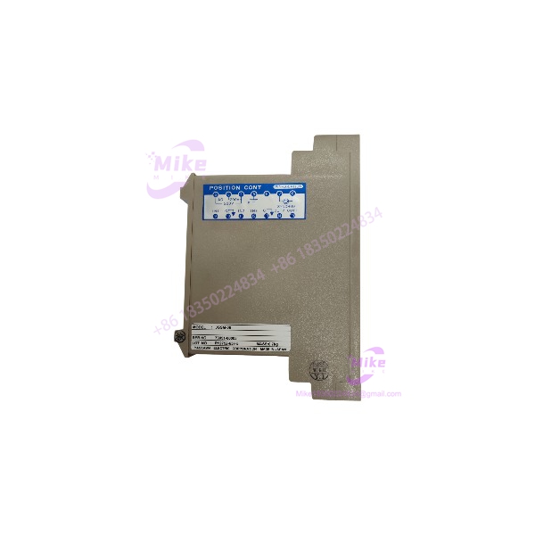
Yaskawa JGSM-06 | VS System Position Controller
Product Introduction
A position-control fault in an older drive system can involve more than the motor or drive itself. The feedback-processing stage may be responsible for converting a detector’s angular-position signal into a usable control voltage. Replacing that module with a generic analog or digital controller is not a safe assumption.
The Yaskawa JGSM-06 is a VS System Module position controller. Yaskawa describes its function as synchronously rectifying the synchro signal from a YVGC-500W displacement detector and converting it into a DC voltage proportional to rotational angle. A signal-mixing function is also provided to obtain the deviation between the position signal and the command signal.
This is a specialized legacy control component. Buyers should confirm the installed VS system configuration, detector type, signal wiring, and original module designation before ordering a replacement. The JGSM-06 should not be represented as a standalone servo amplifier, general-purpose PLC I/O module, or universal position controller.
JGSM-06
Key Technical Specifications
- Manufacturer: Yaskawa Electric Corporation
- Model: JGSM-06
- Series: VS System Module
- Module Classification: Position controller
- Position Feedback Input: Synchro (selsyn) signal
- Associated Displacement Detector: YVGC-500W
- Signal Conversion: Synchronous rectification of synchro signal
- Output: DC voltage proportional to rotational angle
- Signal Mixing: Provides deviation signal between detected position and command signal
- Intended Role: Position feedback and deviation processing within a compatible control arrangement
- Engineering Documentation: Yaskawa JGSM-06 instruction manual, document TO-C730-30.7B
- Secondary Part Number Reference: 73051-00060; physical-label verification recommended
Specification limitations: The official product information confirms the module’s function, but the sources reviewed do not establish a complete model-specific electrical rating, output range, connector pinout, or dimensional drawing. Do not infer these details from unrelated JGSM-series modules or reseller descriptions.
Global Sourcing & Live-Test SOP
The JGSM-06 should be inspected as a signal-processing component within a legacy position-control system. A simple power-on check is not sufficient to establish functional condition.
1. Inbound Verification
- Photograph the complete nameplate and confirm .
- Record any additional part number, serial number, and revision markings.
- Compare the physical unit with the original machine’s installed module.
- Inspect the housing, terminals, connectors, and mounting points for damage.
- Check for corrosion, contamination, loose hardware, or signs of prior repair.
- Photograph all switches, potentiometers, and adjustment positions before handling.
- Confirm whether the unit is supplied with any accessories or documentation.
2. Controlled Power-Up
- Obtain the applicable Yaskawa instruction manual and verify the required supply voltage and wiring before energizing.
- Use a compatible test arrangement rather than applying an assumed 24 VDC or 220 VAC supply.
- Observe startup behavior and any available status indicators.
- Check for abnormal heating, odor, intermittent operation, or visible damage.
- Do not change calibration adjustments or switch positions without recording the original settings.
3. Signal-Path Validation
- Confirm that the test setup uses the appropriate synchro input and compatible detector arrangement.
- Verify the input and output wiring against the applicable documentation.
- Apply controlled test signals only within documented operating limits.
- Check whether the output DC voltage responds consistently to changes in the simulated position input.
- Verify the signal-mixing/deviation function where the correct command and feedback signals are available.
- Record observed output behavior and any instability or abnormal response.
4. Extended Functional Run
Where a suitable test setup is available, perform an extended operating test using the documented electrical configuration.
Monitor:
- Startup consistency
- Output stability
- Response to changing position input
- Signal-mixing behavior
- Abnormal heating
- Intermittent operation or drift
Record the test duration, applied supply, test arrangement, and measured results. Do not claim a full functional test if only visual inspection or a basic power check was completed.
5. Final Preparation
- Record the complete model designation and any cross-reference markings.
- Document the actual test scope and results.
- Photograph the connectors and adjustment positions.
- Protect terminals and electronic components against impact and electrostatic discharge.
- Use ESD-safe packaging where appropriate.
- Clearly identify whether the item is tested, untested, or sold for parts/repair.
Field Engineer’s Pitfall Guide
❗ Do not confuse position control with servo power amplification
The is documented as a position controller that processes synchro signals and provides a DC voltage proportional to rotational angle. It should not be listed or installed as a servo power amplifier without independent evidence supporting that classification.
❗ Verify the detector and signal interface
Yaskawa identifies the YVGC-500W displacement detector in the functional description. Confirm the actual detector, signal wiring, and control-system arrangement before assuming compatibility with another feedback device.
❗ Do not rely on reseller electrical specifications without OEM confirmation
Secondary listings provide inconsistent technical descriptions for the . Avoid assuming a supply voltage, output range, or universal PLC/servo compatibility based on generic marketplace copy. Verify the exact module against Yaskawa documentation and the machine’s original wiring.
Intent-Driven FAQ
What is the Yaskawa ?
The is a Yaskawa VS System Module position controller. It processes synchro-based position feedback and provides a DC voltage proportional to rotational angle.
What does the do?
It synchronously rectifies a synchro signal from a compatible displacement detector, converting it into a DC voltage proportional to rotational angle. Its signal-mixing function allows a deviation signal to be obtained from the command and feedback signals.
Is the a PLC I/O module?
It is documented as a VS System Module position controller, not a general-purpose PLC digital or analog I/O card. Its intended role is position-signal processing within a compatible control arrangement.
Which detector is associated with the ?
Yaskawa’s product description identifies the YVGC-500W displacement detector as the source of the synchro signal used by the . Confirm the detector and wiring used in the actual machine before replacement.
What power supply does the require?
The reviewed official product page confirms its function but does not provide a complete electrical rating. Verify the supply voltage, wiring, and terminal assignments in the applicable instruction manual before applying power.
Is the hot-swappable?
Do not assume it is. Treat replacement as a controlled, power-off maintenance task unless the specific machine documentation explicitly authorizes live replacement. Follow the applicable Yaskawa and site maintenance procedures.
What should I verify before buying a used ?
Confirm the complete model marking, physical condition, connector arrangement, installed-system compatibility, and seller’s test status. For operational use, request evidence of signal-path testing—not just a photograph showing that the module powers up.
Bottom Line for Buyers
The is a specialized VS System position controller used for synchro-based rotational-position signal processing. Its replacement value depends on matching the original module and preserving the detector, signal wiring, and control-system arrangement.
For procurement, specify the exact model, request clear nameplate and connector photographs, and verify the applicable Yaskawa manual before commissioning. Avoid purchasing based solely on generic claims of PLC or servo compatibility.





