


Description
Siemens 6SC6108-0SN00 | SIMODRIVE 610 3-Axis Power PCB In Stock
Architect’s Product Breakdown
The Siemens 6SC6108-0SN00 is a 3-axis power circuit board assembly designed specifically for the legacy SIMODRIVE 610 AC feed drive platform. Used extensively in 1980s and 1990s CNC machine tools (such as SINUMERIK 3T, 810M, and 880 controller lines), this board mounts inside the drive frame to handle primary power switching and current feedback for three distinct servo axes.
The “A38 8/16A” rating designates the power stage sizing: each of the three axis channels is engineered to deliver 8 Amperes continuous current and up to 16 Amperes peak current during acceleration and deceleration phases. The PCB carries the power transistor/IGBT gate drive isolation circuits, DC bus distribution connections, current sensing shunts, and multi-pin ribbon cable interfaces that mate directly with the corresponding SIMODRIVE 610 regulator/control cards.
Because the SIMODRIVE 610 system has been obsolete for decades, replacing a failed 6SC6108-0SN00 board with the exact OEM configuration is critical. Swapping with mismatched revision boards (e.g., single-axis or different current rating variants like 12/24A) will cause power stage timing mismatches, tripping the main line contactor or throwing overcurrent alarms on the CNC CNC controller.
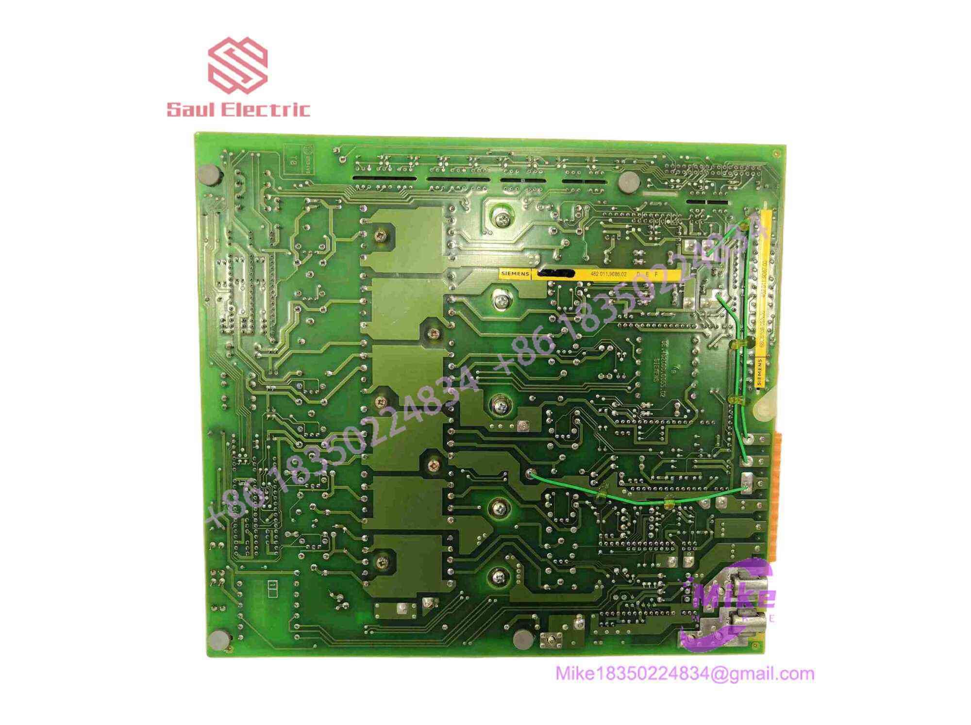
6SC6108-0SN00
Key Technical Specifications
| Parameter | Technical Specification |
| Manufacturer | Siemens AG |
| Product Line | SIMODRIVE 610 AC Feed Drive System |
| Part Number | 6SC6108-0SN00 |
| Module Type | Power Circuit Board Assembly (APCB Power Unit) |
| Axis Configuration | 3-Axis Multi-Drive Capabilities |
| Current Output Rating | A38 Frame (8A Continuous / 16A Peak per Axis) |
| Cooling Method | Forced air via central drive frame fan assembly |
| Form Factor | Multi-layer stacked PCB with integrated heat sink interface bracket |
| Interfacing | Edge-card ribbon connectors for control card feedback & gate signals |
| Weight | ~2.0 kg (~4.4 lbs) |
Field Engineer’s Pitfall Guide (Unique Value)
- DISCONNECTING BOARD BEFORE DC BUS VOLTAGE DISCHARGES: Never pull or service the 6SC6108-0SN00 board immediately after removing main power. The SIMODRIVE 610 intermediate DC link bus holds high voltage (approx. 300V to 600V DC) inside large filter capacitors. Wait at least 5–10 minutes after powering off, and verify with a multimeter that the DC bus terminals read below 50V DC before touching the board.
- INSUFFICIENT THERMAL PASTE ON REPLACEMENT INSTALLATION: Ensure the rear power transistor/module mounting surfaces are cleaned and fresh thermal compound is applied. The power stage transfers heat directly to the drive frame’s central heatsink. Re-installing the board without clean thermal grease will cause localized thermal runaway, destroying the IGBTs within minutes of running under load.
- BENDING MULTI-PIN EDGE CONNECTORS DURING SLOT INSERTION: Do not force the board into the drive rack guide slots. The multi-pin ribbon and edge connectors must align perfectly. Forcing a misaligned board will bend or break the connector pins, causing intermittent phase-loss faults (e.g., axis drive enable dropouts) that are extremely difficult to diagnose.
QA & Testing SOP (Transparency)
- Visual & Structural Audit: Microscopic inspection of high-current PCB traces, solder joints, power resistors, and gate drive optocouplers for thermal stress, cracking, or component bulging.
- Static Power Component Diode Check: Multimeter forward/reverse diode drop tests across all internal power transistors/IGBTs and bridge diodes to ensure no dead shorts exist on any of the 3 output phases.
- Low-Voltage Gate Circuit Test: Validation of driver stage optocouplers and signal conditioning components to ensure symmetrical gate firing pulses across all channels.
- Live SIMODRIVE 610 Bench Load Test: Board installed in a reference 3-axis SIMODRIVE 610 chassis connected to three 1FT5 AC feed motors. Run under load to verify balanced phase currents (8A continuous) and current feedback accuracy.
- Anti-Static & Protective Packaging: Reset, thoroughly cleaned, sealed inside conductive anti-static bags, and packed with high-density impact foam in heavy-duty shipping cartons.
Technical FAQ
What does “A38 8/16A” mean on the 6SC6108-0SN00 label?
“A38” designates the physical current class and frame size for the board. “8/16A” indicates that each of the three axis channels provides 8 Amps continuous output current and can handle 16 Amps peak surge current during short dynamic braking or acceleration moves.
Can I use the 6SC6108-0SN00 in a 1-axis or 2-axis SIMODRIVE 610 rack?
The 6SC6108-0SN00 is designed for a 3-axis drive slot. While it physically fits the multi-axis drive frame, using it in place of a 1-axis or 2-axis power board (such as the 6SC6108-0SG series) requires the control rack and cabling harness to be configured for a 3-axis rack. It is best practice to replace failed boards with the exact same axis count model.
Is the SIMODRIVE 610 series compatible with SIMODRIVE 611 modules?
No. SIMODRIVE 610 is an older generation system with completely different card mechanical dimensions, connector pinouts, bus voltages, and control signaling than SIMODRIVE 611 or 611 Digital platforms. They are not cross-compatible.
What are the most common failure modes on this power PCB?
The most common failures on aging 6SC6108-0SN00 boards are shorted output power transistors (IGBTs/Darlingtons) due to thermal fatigue, blown gate drive resistors, and degraded solder joints on the high-current DC bus input terminals caused by years of thermal cycling.





