

Description
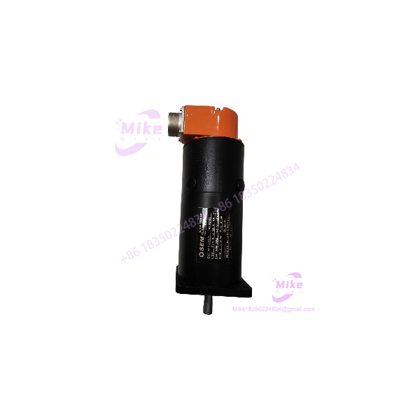
SEM MTS30M4-38 | Industrial Servo Motor, High-Torque DC Unit
Architect’s Product Breakdown
The SEM MTS30M4-38 operates as a rugged permanent magnet direct current servo motor engineered for demanding industrial positioning and speed control applications. Within traditional automation architectures, this specific model delivers rapid acceleration profiles and precise torque linearity, making it a staple in legacy machine tool retrofits, converting equipment, and high-precision winding machinery where dynamic response is critical.
Integrating this hardware into an existing drive enclosure requires careful attention to brush maintenance, commutator condition, and armature current limits. Because this motor relies on direct mechanical commutation, thermal management and ambient cabinet airflow are vital to prevent premature brush wear and thermal degradation of the field magnets. Field engineers must also ensure that feedback devices, such as tachometers or encoders coupled to the shaft, are properly shielded against electromagnetic interference generated by adjacent switching amplifiers.
Furthermore, proper mechanical alignment of the MTS30M4-38 is essential for maximizing service life and minimizing vibration across high-speed operational cycles.
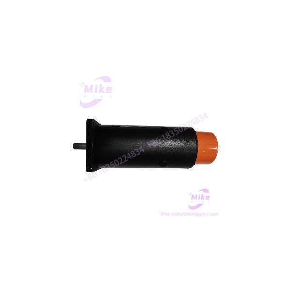
MTS30M4-38
Key Technical Specifications
| Parameter | Specification |
| Manufacturer | SEM (Specialist European Motors) |
| Model Designation | MTS30M4-38 |
| Motor Type | Permanent Magnet DC Servo Motor |
| Excitation | Permanent Magnet |
| Cooling Method | Totally Enclosed Non-Ventilated (TENV) / Fan Cooled options |
| Insulation Class | Class H Winding Insulation |
| Ambient Operating Temperature | 0°C to 40°C |
| Max Operating Speed | Up to 4,000 r/min |
| Enclosure Protection | IP54 Industrial Rating |
| Mounting Configuration | Flange Mount with Pilot |
Field Engineer’s Pitfall Guide
- WARNING: Brush Seating and Wear. Never run a replacement motor at full rated speed without inspecting the carbon brushes first. I once watched a technician commission a fresh install of the MTS30M4-38 without checking the brush bedding, resulting in heavy sparking, commutator pitting, and catastrophic failure within the first twelve hours of operation.
- WARNING: Armature Overcurrent Spikes. Ensure the connected DC servo drive current limit parameters are precisely tuned to the motor’s continuous and peak ratings. Exceeding thermal thresholds will demagnetize the permanent magnets, permanently ruining the torque constant of the unit.
- WARNING: Mechanical Alignment Errors. Always use a dial indicator to verify concentricity when coupling this model to a gearbox or lead screw; angular misalignment will destroy the front shaft bearing under high radial loads.
QA & Testing SOP
- Visual & Origin Verification: Inspect the outer frame for paint chipping, verify OEM nameplate stamped data against factory engineering sheets, and check terminal leads for insulation cracks.
- Winding Resistance & Insulation Test: Measure armature and field circuit resistance with a micro-ohmmeter, followed by a 500V DC megger test to confirm zero leakage current to the motor frame.
- Commutator Inspection: Verify smooth concentricity of the commutator segments and ensure undercutting depth meets exact factory tolerances.
- Dynamic No-Load Run Test: Couple the MTS30M4-38 to an isolated DC power supply on a test bench to monitor vibration levels, current draw, and brush commutation spark suppression across varying speeds.
- Packaging: Seal in heavy-duty anti-corrosion barrier bags and pack with high-density shock-absorbing foam inside a reinforced crate.
Technical FAQ
Can I drive this DC servo motor with a modern AC pulse-width modulated inverter?
No. The requires a compatible linear or pulse-width modulated DC servo drive designed specifically for permanent magnet brushed motors.
What routine maintenance is required for continuous industrial operation?
Inspect carbon brushes every 2,000 operating hours for wear, and clean carbon dust accumulation from the commutator chamber using dry compressed air.
Does this model include an integrated tachometer or encoder feedback device?
Feedback configurations vary by specific suffix build; verify the exact wiring schematic on the terminal housing to determine if an internal tachometer or separate encoder is fitted.
What is the primary cause of premature bearing failure on this frame size?
Excessive belt tension or direct radial side-load exceeding the manufacturer’s maximum rating will rapidly fatigue the internal ball bearings.





