

Description
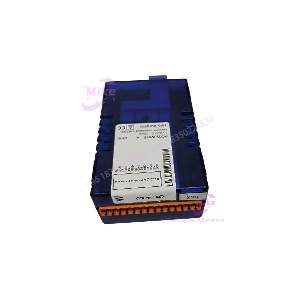
Saia Burgess PCD3.W315 | Analog Input Module Key Spec Data
Architect’s Product Breakdown
The Saia Burgess PCD3.W315 operates as an analog input module within modular programmable logic controller architectures, bridging field sensors with core processing units. In continuous industrial and building automation environments where precise voltage monitoring is required, maintaining signal integrity across multiple channels is essential to prevent data skew. This specific module model accommodates up to 8 independent voltage input channels, translating analog process variables into digital values for internal controller logic processing.
Deploying or replacing this expansion module model requires strict attention to shielding practices and terminal wiring. When performing maintenance swaps, engineers must ensure that field sensor commons are properly terminated and that input voltages do not exceed the specified maximum thresholds. Omitting proper cable shielding or running analog signal wires parallel to high-voltage power lines can introduce electromagnetic interference, resulting in erratic analog readings and process instability.
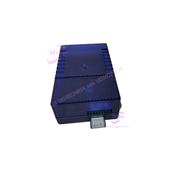
PCD3.W315
Key Technical Specifications
- Manufacturer: Saia Burgess Controls (Honeywell)
- Product Category: Analog Input Module
- Part Number / Catalog No.: PCD3.W315
- Number of Channels: 8 analog input channels
- Input Signal Range: 0 to 10 V DC voltage input
- Termination Type: Removable plug-in spring or screw terminal blocks (accommodating up to 1.5 mm^2 wire)
- Operating Temperature Range: 0°C to +55°C (standard industrial threshold)
- Relative Humidity Limit: 10% to 85% (non-condensing)
- Mounting Type: DIN Rail / PCD3 Modular System Rack
- Weight: Approximately 100 g
Field Engineer’s Pitfall Guide (Unique Value)
- Hot-Swapping Under Power: Never insert or remove the PCD3.W315 module while the rack power supply or field circuits are energized. Doing so can arc backplane pins and corrupt local I/O communications.
- Ignoring Cable Shield Grounding: Failing to properly ground the shielding drain wire of analog signal cables at one end will introduce common-mode noise, causing fluctuating or jittery process variable readings.
- Overvoltage Stress: Exceeding the maximum rated input voltage across the input terminals can permanently damage the internal analog-to-digital conversion circuitry.
QA & Testing SOP (Transparency)
- Visual & Origin Verification: Units undergo physical inspection to confirm clean PCB traces, secure housing latches, and authentic OEM labeling.
- Live Test Bench Environment: Modules are inserted into a validation PCD3 test rack powered by regulated supplies to evaluate backplane communication stability.
- Signal Calibration & Loop Testing: Technicians inject calibrated voltage signals (0 to 10 V) across all 8 channels to verify conversion accuracy and channel linearity.
- Anti-Static Packaging: Post-testing units are wrapped in static-dissipative shielding material and packed with protective cushioning foam to prevent transit damage.
Technical FAQ
Can I hot-swap the PCD3.W315 module while the PLC rack is powered? No. I/O modules and terminal blocks must only be inserted or removed when both the PCD controller rack and external power supplies are completely disconnected.
What types of signals does the PCD3.W315 accept? This specific hardware model is designed for 0 to 10 V DC voltage input signals connected directly to its designated input terminals.
What causes fluctuating or unstable readings on an input channel? Unstable readings are typically caused by unshielded signal cables routed near high-voltage lines, loose terminal connections, or grounding loops in the field sensor wiring.
What is the standard warranty status for surplus inventory units? Verified surplus or factory-sealed modules typically carry a 12-month operational warranty covering material and manufacturing defects under standard industrial environments.





