


Description
Safetec BG02.510 | Repeater Panel Control Module
Product Introduction
When an automated sample-extraction smoke detection network on a commercial vessel loses local user-interface feedback, bridge crews lose immediate visibility into cargo hold safety status. The Safetec BG02.510 is not a generic display interface; it functions as a dedicated control and monitoring module built specifically to orchestrate user interactions on Safetec SDS-48 repeater panels.
—though your mileage may vary depending on firmware revision and specific repeater chassis layout—expect robust on-board logic designed to process multi-zone alarm confirmations and system dialogues under harsh marine conditions. It mounts directly behind the panel front door, keeping layout dimensions tight and operator controls within easy reach.
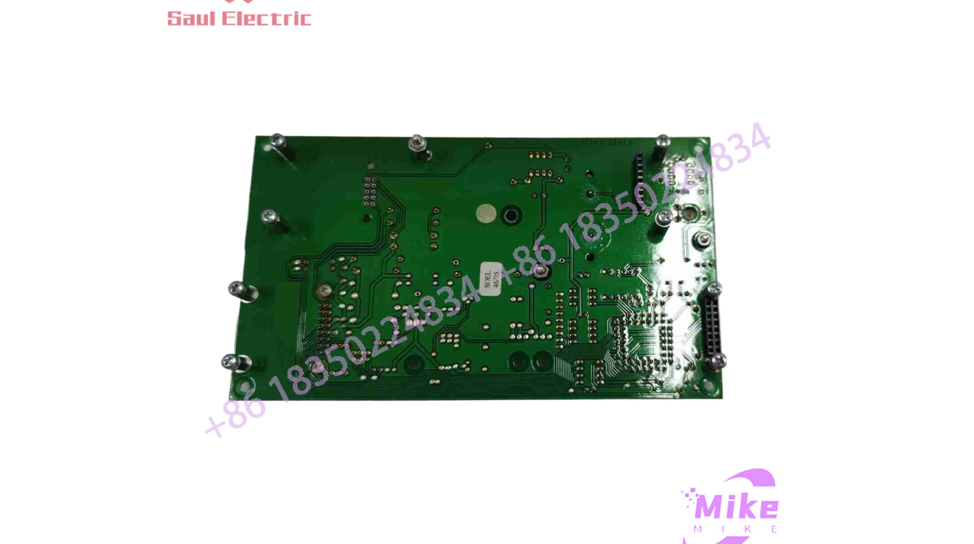
BG02.510
Key Technical Specifications
| Parameter | Specification |
| Compatibility | Safetec SDS02.300 and SDS02.301 Repeater Panels (SDS-48 System) |
| User Interface Elements | Integrated LCD display, status LED indicators, tactile acceptance button |
| Physical Dimensions | 182 mm \times 105 mm \times 38 mm |
| Weight | Approximately 270 g |
| Mounting Position | Rear-mounted directly behind the repeater panel front cover |
| System Compliance | FSS Code Chapter 10, SOLAS Chapter II-2 regulations |
| Operating Environment | Marine vessel engine rooms, cargo control rooms, and bridge environments |
Application Scenarios & Pain Points
- Bulk Carrier Cargo Hold Monitoring: Ships tracking smoke alarms across up to 48 individual cargo spaces rely on this module’s display dialogue to acknowledge, mute, and step through active zone faults quickly.
- Marine Fire & Gas Retrofits: Replacing an unresponsive or water-damaged interface module on an existing SDS-48 repeater network restores full diagnostic control without requiring a complete panel rewiring.
- Offshore Rig Safety Stations: Deployed in environments governed by strict IMO and SOLAS rules where continuous, fail-safe sample extraction monitoring is mandatory.
QA & Live Testing SOP (Trust Signal)
We evaluate critical safety and fire detection modules under rigorous electronic testing protocols before dispatch:
- Visual & Microscopic Inspection: Inspected for conformal coating integrity, connector pin straightness, and solder joint stability on surface-mount components.
- Static Power-Up Test: Board power regulation rails are verified against short circuits using precision meters prior to energizing.
- Processor & Display Verification: Connected to a compatible test rig to check LCD contrast, backlight performance, LED illumination uniformity, and tactile button responsiveness.
- ESD Shielding: Enclosed in anti-static moisture-barrier packaging to protect sensitive integrated circuits during international marine shipping.
Field Engineer’s Pitfall Guide
- ❗ Configuration Dialogue Timing: When interacting with the configuration menu via the “ACCEPT” button, pay close attention to system timeout limits; failing to respond within the automated window will default the setting to “no”.
- ❗ Ribbon Cable Stress: Never yank or pull the internal data ribbon connecting the module to the repeater board during maintenance; pinched or misaligned pins will cause garbled LCD text or complete communication loss.
- ❗ Ungrounded Handling: Touching exposed integrated circuits on this PCB without an ESD wrist strap can induce electrostatic discharge failure on the onboard display controller.
Intent-Driven FAQ
What specific system does the BG02.510 control module belong to?
It is designed specifically for the Safetec SDS-48 sample extraction smoke detection system, operating as the core control component for SDS02.300 and SDS02.301 repeater panels.
Can I use this module to configure fire alarm settings directly?
Yes. By utilizing the integrated display dialogue and the “ACCEPT” push-button interface, technicians can step through configuration options and acknowledge system events.
Is this unit an authentic Safetec OEM component?
Yes. These parts are genuine Safetec fire and gas detection spares sourced from verified marine surplus and distribution networks.
What do the integrated LEDs on the module signify?
They provide visual status queues regarding system health, communication tracking, power supply stability, and active alarm states across the monitored spaces.
Does the module require separate software programming prior to installation?
Generally, it operates as a plug-and-play replacement interface module configured via the host system’s native panel architecture, though firmware versions should match your master rack setup.





