

Description
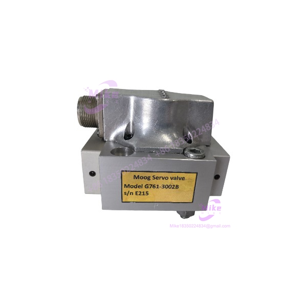
Moog G761-3002B | 10 L/min Hydraulic Servo Valve
Dynamic Product Introduction
When a hydraulic control loop starts hunting, drifting, or responding slowly, the servo valve is one of the first components worth putting under the microscope. The G761-3002B is not a generic proportional valve; it is a two-stage Moog servo valve intended for closed-loop hydraulic control where spool movement must track a relatively small electrical command with controlled flow response.
The G761-3002B is rated for 10 L/min (2.5 gpm) at the specified 35 bar (500 psi) pressure drop per spool land, with a ±40 mA command specification. Its high-response configuration uses a nozzle-flapper pilot stage and mechanical feedback, making the valve appropriate for applications requiring controlled position, speed, pressure, or force.
The exact suffix matters. The G761-3002B corresponds to the H10JOGM4VPL configuration in Moog’s preferred-model documentation. That designation encodes several important characteristics, including the 10 L/min flow class, 315 bar aluminum-body pressure rating, spool configuration, pilot-stage design, center spool position, internal pilot supply, FKM seals, connector arrangement, and ±40 mA command. Do not substitute a visually similar 761 Series valve solely because its flange and connector appear identical.
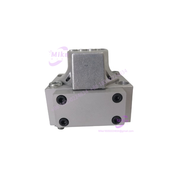
G761-3002B
Key Technical Specifications
- Manufacturer: Moog
- Model: G761-3002B
- Series: G761 / 761 Series
- Type designation: H10JOGM4VPL
- Valve configuration: Two-stage, mechanical-feedback servo valve
- Rated flow: 10 L/min (2.5 gpm)
- Rated flow condition: 35 bar (500 psi) pressure drop per spool land
- Maximum operating pressure: 315 bar (4,500 psi)
- Body material: Aluminum
- Valve response: High response
- Spool position without electrical signal: Center position
- Pilot connection: Internal supply, port P
- Seal material: FKM / fluorocarbon
- Valve connector: 4-pin MS threaded connector over P-side
- Rated command current: ±40 mA
- Pilot-stage technology: Nozzle-flapper
- Control configuration: 4-way flow control
- Application: Closed-loop hydraulic position, speed, pressure, and force control
Moog’s current catalog lists the G761-3002B alongside the 4, 19, 38, and 63 L/min preferred models. The model-specific rated flow is therefore not an approximate marketing figure—it is the defined 761 Series flow classification.
Global Sourcing & Live-Test SOP
For a surplus or replacement , visual inspection alone is not enough. A servo valve can look excellent externally while having contamination, spool wear, degraded seals, or a damaged pilot stage.
1. Inbound Verification
Start with the complete identification plate and serial information.
Record:
- Complete type designation where visible
- Serial number
- Factory identification/revision markings
- Connector configuration
- Port and mounting-face condition
- Seal condition
- Evidence of previous hydraulic service
The type designation should be compared against the required machine specification. For this model, the documented designation is H10JOGM4VPL.
Do not classify a valve as an exact replacement merely because the first seven characters match. Moog uses additional configuration characters to specify pressure/body material, spool design, pilot stage, spool position, pilot supply, seals, connector, and command current.
2. Hydraulic Simulation
A meaningful live test requires a controlled hydraulic test stand—not simply an electrical continuity check.
The test setup should include:
- Clean hydraulic supply
- Filtration appropriate to the valve/application
- Regulated pressure
- Calibrated pressure gauges/transducers
- Controlled electrical current source
- Flow measurement
- Appropriate hydraulic load
- Emergency pressure isolation
For the , verify response around the null region before driving the valve toward full command. The rated flow is specified at a particular pressure drop, so actual flow will change with pressure differential. Moog provides the relationship using the square-root flow equation for the valve’s sharp-edge orifice behavior.
3. Electrical Diagnostics
The electrical test should confirm that the command circuit behaves correctly before hydraulic loading.
Verify:
- Coil resistance against the applicable Moog specification
- Connector pin condition
- Command-current polarity
- Current at zero command
- Positive command response
- Negative command response
- Null behavior
- Full command response
A calibrated current source and precision multimeter are preferable to a basic bench power supply. The ±40 mA specification is particularly important: substituting a control amplifier intended for a different coil/current configuration can produce incorrect spool response or potentially damage the actuator circuit.
4. Hydraulic Performance Test
With clean hydraulic fluid and controlled pressure, evaluate:
- Null leakage
- Flow versus command current
- Positive and negative flow response
- Hysteresis
- Repeatability
- Response symmetry
- External leakage
- Abnormal noise
- Spool stability
A 24-hour powered/hydraulic endurance test can be added for production-critical replacement inventory. Record temperature, pressure, command current, and flow periodically rather than relying on a simple pass/fail observation.
5. Final Preparation
Before shipment, record the complete model and type designation.
The test report should identify , H10JOGM4VPL, measured electrical values, hydraulic test conditions, and observed flow behavior. Protect the connector and hydraulic ports from contamination, use appropriate caps, and package the valve to prevent impact damage.
For hydraulic servo valves, cleanliness is part of the test procedure—not merely a packaging concern.
The Field Engineer’s Pitfall Guide
❗ Do not substitute the valve based only on the G761 family number.
The ordering structure contains multiple configuration fields. Pressure rating, spool/bushing design, pilot stage, fail position, pilot supply, seal material, connector position, and command-current configuration can all change. I’ve seen apparently interchangeable hydraulic valves create control problems because one configuration detail was ignored.
❗ Do not assume ±40 mA means every 761 Series valve uses the same electrical drive.
The is specifically listed at ±40 mA. Moog’s ordering system supports several command-current options, including ±4, ±8, ±15, ±40, ±50, and ±200 mA depending on configuration. The amplifier must match the actual valve designation.
❗ Do not install a servo valve into a contaminated hydraulic circuit and blame the valve when the loop becomes unstable.
Two-stage servo valves are highly sensitive to hydraulic cleanliness. A particle entering the pilot stage or spool area can cause sticking, null shift, or degraded response. In field troubleshooting, filtration condition and hydraulic cleanliness should be checked alongside electrical command signals—not after the valve has already been removed and returned to the supplier.
Intent-Driven FAQ
What is Moog used for?
The is a two-stage electrohydraulic servo valve for closed-loop control of hydraulic position, speed, pressure, or force. Its documented rated flow is 10 L/min (2.5 gpm), with a ±40 mA command specification.
s the a proportional valve?
It is more accurately described as a two-stage servo valve. The 761 Series uses a nozzle-flapper pilot stage with mechanical feedback. That architecture is intended for precise closed-loop hydraulic control rather than basic on/off directional switching.





