

Description
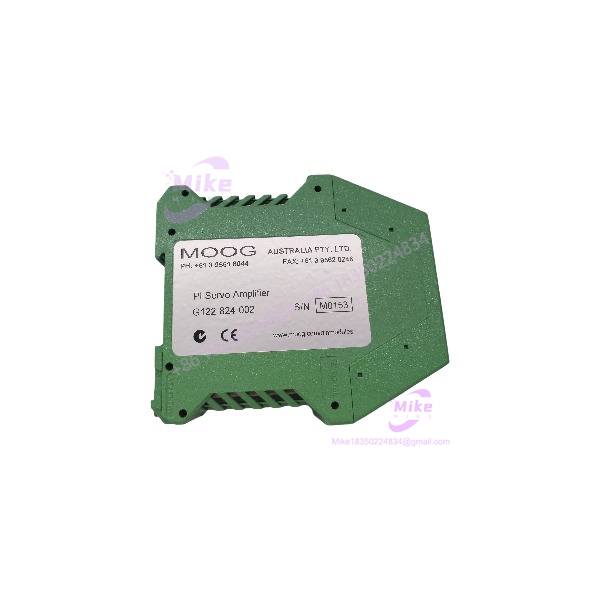
MOOG G122-824-002 | DIN Rail P-I Servo Amplifier
Dynamic Product Introduction
The MOOG G122-824-002 is a dedicated analog servo amplifier for closed-loop hydraulic motion control. It sits between the control system, feedback transducer, and electrohydraulic servo valve, providing the proportional and integral processing needed to close the position or process-control loop. This is very different from a conventional PLC analog output card: the G122-824-002 is designed around servo-loop dynamics and valve control rather than general-purpose signal generation.
Moog describes the unit as a general-purpose, user-configurable P-I servo amplifier. Internal selector switches allow proportional control, integral control, or both, while front-panel adjustments provide access to important loop parameters. The architecture also includes feedback transducer excitation, an enable function, dither, an in-position output, and signal test points.
The G122-824-002 was introduced as an improved version of the G122-824-001. Moog specifically added a 4–20 mA option for Input 2, an output-step push button for loop optimization, and improved thermal performance. That makes the -002 version more flexible for applications where both command and feedback signals need current-loop compatibility.
In practical terms, this is the kind of module found in turbine governors, hydraulic actuator systems, industrial positioning equipment, and other applications where a servo valve must respond predictably to a closed-loop command. An ABB hydro-power reference, for example, shows the G122-824-002 used in a distribution-valve servo-control arrangement with LVDT feedback and 4–20 mA / ±10 V signal interfaces.
G122-824-002
Key Technical Specifications
- Manufacturer: MOOG
- Part Number: G122-824-002
- Product Name: P-I Servo Amplifier
- Series: G122-824
- Application: Closed-loop electrohydraulic servo control
- Supply Voltage: +24 VDC
- Mounting: DIN rail
- Control Functions: P, I, or P + I
- Input 1: Single-ended analog input, configurable
- Input 2: Single-ended analog input, configurable
- Feedback Input: Differential input with zero and gain adjustment
- Analog Signal Types: 4–20 mA and ±10 V, depending on internal configuration
- Output Configuration: Current or voltage, selectable
- Feedback Transducer Excitation: Provided by amplifier
- Dither: Selectable
- Enable Input: Provided
- In-Position Output: Provided
- Front-Panel Interface: LEDs, adjustment potentiometers, and test points
- Installation: Compact DIN-rail enclosure
- Compliance: CE marked
Moog’s own product information confirms the principal functional features, while its application documentation dethe as a user-configurable P-I servo amplifier intended for closed-loop applications.
A key procurement caution: several third-party listings describe the unit as a generic “servo valve driver” or attach unsupported detailed electrical figures to it. Those descriptions should not override the Moog documentation. For a replacement, the actual installed configuration—especially internal selector settings, feedback type, output mode, and valve interface—should be treated as part of the specification.
Global Sourcing & Live-Test SOP
1. Inbound identity check
Start with the physical nameplate and housing markings.
Confirm:
- MOOG identification
- Exact part number
- Hardware/revision information
- Terminal condition
- Housing condition
- DIN-rail mounting hardware
- Front-panel controls
- LED condition
- Evidence of corrosion, contamination, or unauthorized repair
Do not classify the unit simply as a “.” The -001 and -002 versions are not identical.
2. Configuration inspection
Before applying power, document the internal selector-switch and potentiometer configuration.
Pay particular attention to:
- P / I / PI mode
- Feedback input type
- Input scaling
- Output current/voltage selection
- Dither
- Integral limit
- Gain settings
- Feedback derivative option
- Enable configuration
This is one of those cases where two visually identical amplifiers can behave very differently because of internal settings.
3. Power verification
The requires a +24 VDC control supply. Verify the bench supply before connecting the amplifier and check polarity carefully.
Do not use the 24 V rating as permission to connect the unit directly into an unknown field circuit. The connected valve, feedback transducer, and signal source must be considered as one control loop.
4. Analog signal simulation
A useful bench test uses calibrated signal sources to reproduce the actual control architecture.
Depending on the intended configuration, simulate:
- ±10 V command
- 4–20 mA command
- ±10 V feedback
- 4–20 mA feedback
- Enable signal
- Feedback transducer excitation
Measure the amplifier response with a calibrated multimeter and suitable current/voltage measurement equipment.
5. Output verification
Test the selected output mode rather than assuming the amplifier is configured for current output.
Verify:
- Output zero
- Output span
- Direction of response
- Gain adjustment
- Integral response
- Enable behavior
- Dither behavior
- Step-button response
- In-position output
For a hydraulic application, a bench electrical test is necessary but not sufficient. Final acceptance should include the actual servo valve and feedback device whenever possible.
6. 24-hour heat run
For a critical spare, conduct a controlled 24-hour energized test after functional verification. Monitor supply current, enclosure temperature, output stability, LED status, and drift in the command-to-output relationship.
For an analog servo amplifier, thermal drift matters. A unit that behaves correctly for five minutes may still have a problem that appears after sustained operation.
Field Engineer’s Pitfall Guide
1. Deat as a generic analog amplifier.
Its internal configuration directly affects loop behavior. A technician can replace the hardware correctly and still produce an unstable hydraulic system if the new unit’s P/I settings, feedback selection, or output mode do not match the original.
A practical field rule: photograph or record every adjustment and switch position before removing the old amplifier.
2. Do not assuand are functionally identical.
The -002 is a functional replacement for the -001, but Moog specifically added the 4–20 mA Input 2 option, output-step push button, and improved thermal performance. Applications documentation for the two versions should not be mixed casually.
If a legacy machine still carries a -001, record the original application settings before migrating to the -002.
3. Do not substitute G122-829-001 without checking the wiring.
Moog identifies G122-829-001 as a functional replfor , but explicitly notes that it has a different pinout. That makes it a migration component, not a simple unplug-and-replace spare.
In field service, this is exactly the type of change that can produce an apparently healthy amplifier with completely incorrect valve or feedback behavior. Compare terminal assignments and update the wiring documentation before installation.
Intent-Driven FAQ
What OOG ?
The is a P-I servo amplifier designed for closed-loop electrohydraulic control. It provides configurable proportional and integral control and interfaces with analog command and feedback signals.
What power oes use?
The amplifier operates from a +24 VDC supply. The supply should be verified before connecting the module, particularly when commissioning a replacement into an existing control cabinet.
Can accept 4–20 mA signals?
Yes. The -002 revision adds a 4–20 mA option for Input 2. The feedback input can also be configured for 4–20 mA or ±10 V depending on the application configuration.
the provide both P and I control?
Yes. Internal selection permits proportional control, integral control, or combined P + I control. The exact settings should be established from the original machine’s loop requirements rather than selected arbitrarily during replacement.





