

Description
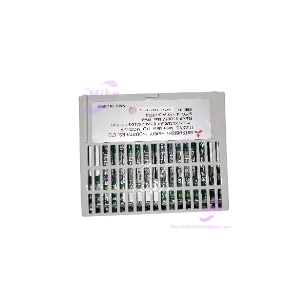
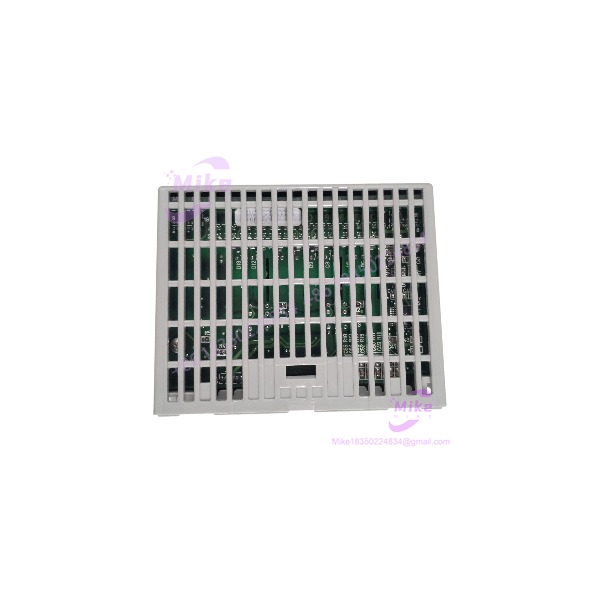
Mitsubishi FXAOM01AD | 8-Channel Analog Output Module
Dynamic Product Introduction
The Mitsubishi FXAOM01AD is an eight-channel analog output module intended to move controller data into real-world analog control loops. Instead of switching a discrete output ON or OFF, it provides continuously variable current signals that can be used by devices such as control valves, motor drives, positioners, and other analog field equipment.
That makes the module a useful component in process-oriented automation where the PLC or control system needs several independent analog commands in a relatively compact hardware footprint. Available product references consistently identify FXAOM01AD as an 8-channel dual analog output module.
The detailed Mitsubishi Hitachi Power Systems documentation for FXAOM01AD-1, a closely related revision, specifies individually isolated 0–20 mA / 4–20 mA outputs, 12-bit resolution, a 12 ms data-update time, and a maximum load resistance of 550 Ω.
For procurement, that revision distinction deserves attention. Do not assume that every unit carrying the FXAOM01AD family designation has identical electrical characteristics without checking its nameplate and applicable documentation. On a legacy control system, the output range, isolation arrangement, terminal assignment, and host-interface architecture all matter.
FXAOM01AD
Key Technical Specifications
- Manufacturer: Mitsubishi
- Part Number: FXAOM01AD
- Product Category: PLC / industrial automation analog output module
- Analog Outputs: 8 channels
- Output Type: Analog current output
- Supported Current Ranges: 0–20 mA and 4–20 mA on the documented -1 configuration
- Resolution: 12 bit on the documented -1 configuration
- Load Resistance: 0–550 Ω on the documented -1 configuration
- Channel Isolation: Individual isolation on the documented -1 configuration
- Data Update Time: Approximately 12 ms
- Self-Diagnostics: Watchdog, low-supply monitoring, bus timeout and readback-related diagnostics on the documented -1 version
- Status Indicator: Three-state LED indication on the documented -1 version
- Supply: 24 VDC ±10% plus FLEX I/O bus power on the documented -1 architecture
- Operating Temperature: 0 to 55°C on the documented -1 version
- Relative Humidity: 35–95% RH during operation, non-condensing
- Approximate Dimensions: 94 W × 46 H × 75 D mm for the documented -1 version
The detailed -1 specification identifies 8 individually isolated channels, 12-bit conversion, ±0.1% FSD relative accuracy, temperature drift of no more than 100 ppm/°C, and 0–550 Ω load resistance. It also specifies 24 VDC ±10% auxiliary supply requirements and a 0–55°C operating range.
Because the documentation located for the detailed electrical specification is specifically marked , these values should be confirmed against the physical revision before being treated as guaranteed specifications for every unit.
Global Sourcing & Live-Test SOP
An analog output module should never be accepted solely because all LEDs appear normal. The meaningful test is whether each channel produces the correct electrical signal across its usable operating range.
1. Inbound verification
- Confirm the complete part number on the module label.
- Record any suffix, revision, or manufacturing code.
- Inspect the terminal block and connector for damage.
- Check for corrosion, contamination, or signs of overheating.
- Inspect the PCB enclosure and mounting hardware.
- Verify that the physical module matches the expected host-system architecture.
- Photograph the nameplate before installation.
For the , the suffix deserves particular attention because detailed specifications found for the related should not automatically be transferred to an earlier or differently configured unit.
2. Power and communication check
Install the module in an appropriate test rack or host system.
Verify:
- Supply voltage
- Module recognition
- Status LED behavior
- Communication with the host controller
- Absence of diagnostic faults
- Stable operation after warm-up
Do not connect a field actuator during the initial electrical test.
3. Analog output simulation
Connect each channel to a calibrated current measurement instrument.
A suitable test sequence should verify representative values such as:
- 0% output
- 25% output
- 50% output
- 75% output
- 100% output
For a 4–20 mA configuration, this means checking the corresponding current levels across the range. For a 0–20 mA configuration, verify the full zero-to-span behavior separately.
Use a calibrated process meter rather than relying solely on the PLC’s displayed command value. The controller can report 50% while the physical output stage is producing something materially different.
4. Load testing
Where the application requires a significant loop load, test the output against an appropriate resistance or calibrated loop simulator.
The do specification gives a maximum load resistance of 550 Ω.
Do not exceed the applicable module specification simply to prove a worst-case condition.
5. Channel isolation check
For versions specified as individually isolated, verify that one channel’s output behavior does not create unexpected interaction with another channel.
This is especially important when the module is used to control several independent field devices with different power supplies or grounding arrangements.
6. Readback and diagnostic verification
Where supported by the installed revision, test the module’s diagnostic functions.
The do includes watchdog, low-voltage, bus-timeout, redundancy-connector, and readback-related diagnostics.
Record the diagnostic state before and after each test.
7. Extended heat run
For a production spare, operate the module continuously with representative output activity.
Monitor:
- Output accuracy
- Channel stability
- Supply current
- Module temperature
- Communication status
- Diagnostic behavior
- Intermittent channel faults
A 24-hour heat run is appropriate when required by the internal procurement SOP.
8. Final inspection record
Document the exact part number and revision, host system, test instrument used, measured current at several setpoints, diagnostic results, and any channels that require further investigation.
For an analog module, measured values are much more useful than simply recording “tested OK.”
Field Engineer’s Pitfall Guide
1. Do not confuse an analog output module with a digital output card.
The provides analog control signals. It is intended for applications where the receiving device expects a variable current command.
If a machine drawing calls for a relay contact, 24 VDC transistor output, or another discrete interface, this module is the wrong hardware regardless of its eight-channel count.
2. Verify the exact output range before connecting a field device.
A 4–20 mA loop and a 0–20 mA loop are not interchangeable from a commissioning standpoint. The receiving instrument, PLC configuration, scaling, and alarm strategy all need to agree.
The do supports both ranges, but the actual module revision should be verified before wiring.
3. Do not overlook loop resistance and grounding.
The do allows up to 550 Ω load resistance. A long cable run, several series devices, isolators, and an incorrectly selected receiver can consume that available loop voltage.
In field deployments, a channel that reads correctly with a bench meter can still fail after the actual field device is connected. Test the complete loop where practical.
Intent-Driven FAQ
1. What is the Mitsubishi ?
The Mitsubishi is an 8-channel analog output module used to provide variable analog control signals to external industrial equipment. Product references identify it specifically as a dual analog output module with eight channels.
2. How many analog outputs does provide?
It provides 8 analog output channels.
3. Does provide 4–20 mA outputs?
The documented version supports 4–20 mA and 0–20 mA output ranges. Because the exact unit may carry a different revision designation, verify the physical module documentation before assuming those ranges apply without qualification.
4. What resolution does have?
The detailed specification gives 12-bit resolution.
5. What is the maximum load resistance?
For the do configuration, the maximum specified load resistance is 550 Ω. The actual allowable load should be checked against the exact module revision and loop configuration.
6. Are the analog channels isolated?
The do provides individual channel isolation. This should be verified against the exact revision before using isolation as a design assumption.
7. What should be checked when buying a used ?
Verify the complete model marking and revision, eight-channel operation, output range, analog accuracy, channel isolation where applicable, connector condition, host-system compatibility, and physical output current under load. A calibrated current measurement test is strongly preferable to a simple power-up inspection.





