

Description
Metso IOP351 | 16-Channel Form A/B Relay Output Module
Product Introduction
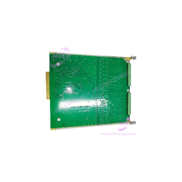
When a legacy control system needs discrete output switching, the relay contact configuration matters as much as the part number. The Metso IOP351 is a 16-channel Form A/B relay output module designed for the maxPAC I/O subsystem. Each channel can be configured for normally open or normally closed operation, making the module relevant to established process-control installations that rely on relay-based field interfaces.
Metso’s maxPAC Hardware Reference Guide specifies switching capacities of up to 5 A at 250 VAC, 3 A at 30 VDC, or 0.3 A at 110 VDC. The guide also documents individual channel status LEDs and configurable output behavior following loss of I/O bus communication. Confirm the installed channel configuration and load requirements before selecting an IOP351 as a replacement.
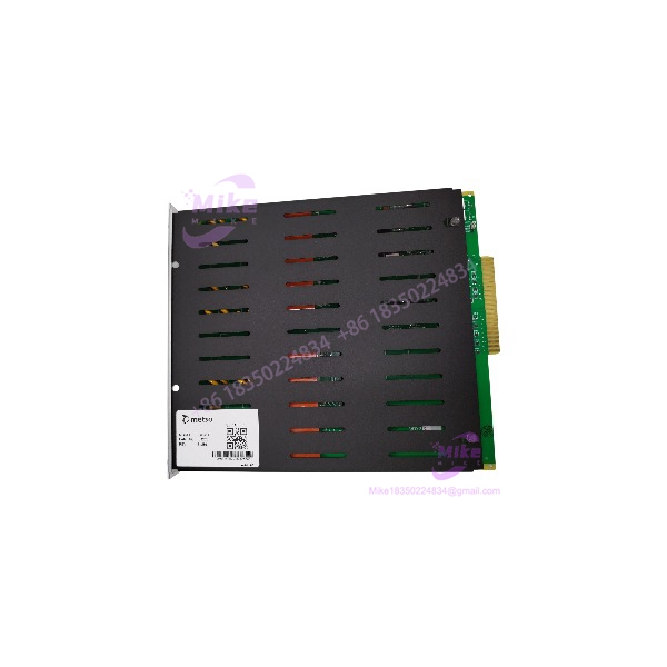
IOP351
Key Technical Specifications
- Model Number: IOP351
- Manufacturer: Metso Automation / MAX Controls
- System Family: maxPAC I/O subsystem
- Module Type: Digital relay output
- Number of Channels: 16
- Relay Contact Type: Form A / Form B
- Default Channel Configuration: Form A
- Form B Configuration: Selected per channel through onboard PCB configuration
- Maximum Switching Capacity:
- 5 A at 250 VAC
- 3 A at 30 VDC
- 0.3 A at 110 VDC
- Expected Mechanical Relay Life: 5 × 10⁶ operations at 180 cycles per minute
- Expected Electrical Relay Life: 10⁵ operations at 20 cycles per minute, resistive load
- Maximum Operating Speed: 20 cycles per minute
- Operating Time: 15 ms maximum, excluding contact bounce
- Release Time: 5 ms maximum, excluding contact bounce
- Output Status Indication: Individual red LED per channel
- Module Status Indication: Green Active LED indicates system power and communication; blinking indicates the module is not being scanned by the DPU
- I/O Bus Address: One address
- Address Range: Digital output modules use the documented 32–254 range
- System Power: 24 VDC supply
- Input Power Consumption: 400 mA from the 24 V system supply
- Communications Watchdog: Output behavior is controlled if I/O bus communication is lost for more than approximately 0.7 seconds
Specifications above are from the Metso maxPAC Hardware Reference Guide. Switching ratings are maximum documented values, not a blanket recommendation for every load type. Verify the applicable contact rating for the actual load, especially inductive loads.
Global Sourcing & Live-Test SOP
For legacy relay output modules, procurement verification should establish model identity, contact configuration, and switching performance. A visual inspection alone cannot confirm relay contact integrity.
Incoming Inspection
- Verify the IOP351 model marking and manufacturer identification.
- Record serial number and board revision, where available.
- Inspect connectors, PCB, relay areas, and edge contacts for corrosion, damage, or repair.
- Photograph the unit and labels for procurement records.
Configuration & Authenticity Review
- Confirm the IOP351 identity against maxPAC documentation.
- Inspect and record each channel’s Form A/Form B configuration where accessible.
- Record the W1 watchdog output setting.
- Verify the module’s intended maxPAC bus address and installation requirements.
Functional Test Procedure
- Use a compatible maxPAC test setup and suitable isolated test equipment.
- Verify module startup and available status indications.
- Command each relay output and verify contact operation.
- Check contact continuity and open/closed behavior against the documented channel configuration.
- Test representative channels under an appropriate load within the documented ratings.
- Verify output behavior during simulated I/O bus communication loss, where supported by the test setup.
Extended Run & Documentation
- Record channels tested, contact configuration, test conditions, and observed results.
- Document any contact resistance, intermittent switching, or abnormal relay behavior.
- Perform an extended operating run if included in the seller’s test scope.
- Package the module in ESD-protective material with suitable cushioning.
Testing transparency: This is a recommended inspection and acceptance procedure, not a claim that a specific has been tested. Actual test results, repair history, warranty, and return terms must be confirmed with the seller.
Field Engineer’s Pitfall Guide
- ❗ Verify Form A versus Form B channel configuration. The supports both contact arrangements, with Form A as the documented default. A replacement’s channel configuration may not match the removed card. Check the onboard configuration against the field wiring and control logic.
- ❗ Respect the load-specific switching limits. The guide lists different maximum ratings for AC and DC loads. Do not treat 5 A at 250 VAC as a universal rating for every DC or inductive application. Confirm the load characteristics and applicable contact limits before commissioning.
- ❗ Check watchdog behavior before returning the module to service. The W1 jumper determines whether outputs reset or hold their last state after loss of I/O bus communication. Confirm the intended fail-state behavior with the site’s control philosophy and process safety requirements.
Intent-Driven FAQ
Q1: What is the Metso used for?
The provides 16 relay output channels for switching discrete field loads in a compatible Metso maxPAC I/O system.
Q2: Is the a Form A or Form B relay module?
It supports both. Form A is the documented default, and individual channels can be configured for Form B operation through onboard PCB configuration.
Q3: What are the ‘s maximum switching ratings?
The maxPAC Hardware Reference Guide lists 5 A at 250 VAC, 3 A at 30 VDC, and 0.3 A at 110 VDC. Actual suitability depends on the load and applicable contact rating.
Q4: Can the be hot-swapped?
The maxPAC Hardware Reference Guide states that I/O modules may be inserted and withdrawn safely with 24 VDC and field power applied. However, follow the applicable site procedure, verify system configuration and redundancy, and assess process risk before removal or installation.
Q5: What happens if the loses I/O bus communication?
After approximately 0.7 seconds without I/O bus communication, the watchdog controls output behavior. The W1 jumper selects reset or hold-last-state behavior.
Q6: What should I verify before ordering a replacement ?
Confirm the exact model, board revision, channel contact configuration, W1 jumper setting, bus address, and condition of the offered unit. Ensure the contact ratings are suitable for the connected field loads.
Q7: Is the obsolete, tested, or covered by a warranty?
The is a legacy Metso maxPAC module. Confirm current support status, actual unit condition, functional test evidence, and warranty coverage with the seller. No testing or warranty is implied by this listing.





