


Description
LENZE EPL10200-W | 24 VDC Drive PLC
Product Introduction
When an older LENZE machine stops because its controller has failed, replacing the entire automation architecture is usually the most expensive possible first move. The LENZE EPL10200-W is the kind of legacy controller maintenance teams look for when preserving an existing Drive PLC installation is more practical than redesigning the cabinet.
The EPL10200 platform is a LENZE Drive PLC architecture with dedicated supply, digital I/O, analog I/O, and a CAN-based system bus. LENZE mounting documentation identifies the EPL10200 family as a Drive PLC and specifies a +18 to +30 VDC supply range, with a maximum stated current of 4.2 A at 24 VDC for the Drive PLC assembly.
One important procurement warning: public listings for EPL10200-W are inconsistent, with some sellers describing it as a Drive PLC and others attaching unrelated drive or power-module specifications. Do not purchase this model from a generic specification sheet alone. The physical nameplate and exact hardware/software identification should control the replacement decision. LENZE documentation confirms that the EPL10200 family exists within the Drive PLC product line and that software generations extend through V8.0 documentation.
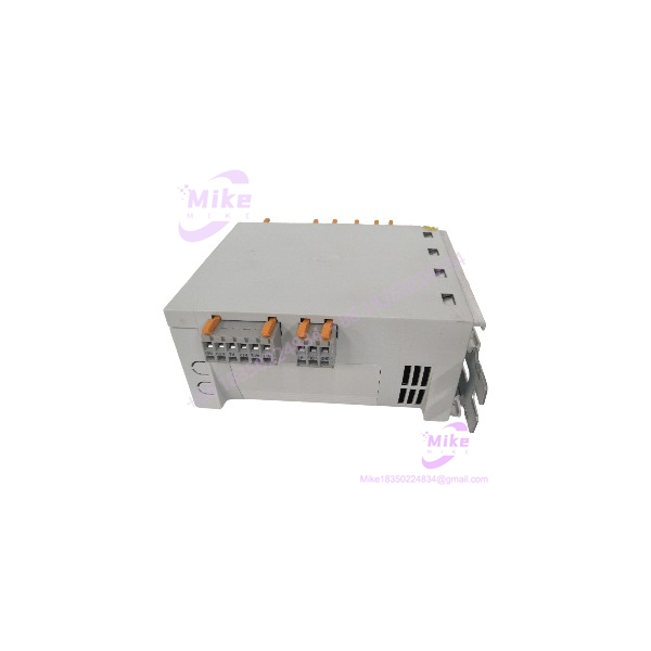
EPL10200-W
Key Technical Specifications
- Manufacturer: LENZE
- Model: EPL10200-W
- Product Family: LENZE Drive PLC
- Controller Type: Industrial Drive PLC
- Supply Range: +18 to +30 VDC
- Nominal Supply: 24 VDC
- Maximum Stated Current: 4.2 A at 24 VDC
- System Bus: CAN
- Digital I/O: Integrated digital input/output terminals
- Analog I/O: Integrated analog input/output terminals
- Programming Environment: LENZE Global Drive PLC development environment
- Application: Drive coordination, machine sequencing, decentralized automation logic
- Mounting: Industrial control cabinet / standard mounting arrangement
- Hardware Revision: Must be verified from the individual unit
- Software Revision: Must be matched to the target application
The LENZE mounting documentation identifies terminal groups for DC supply, digital outputs, digital inputs, analog I/O, and the CAN system bus. It also identifies the EPL10200 family as a Drive PLC architecture.
Application Scenarios & Pain Points
Legacy Machine Recovery
Without an EPL10200-family spare:
A controller failure can trigger an uncomfortable chain reaction—PLC program recovery, drive communication verification, cabinet rewiring, commissioning, and production acceptance.
With a correctly matched replacement:
The maintenance team can focus on controller replacement and application recovery rather than immediately redesigning the entire machine.
That difference matters on equipment that has been running for 10, 15, or even 20 years.
CAN-Based Drive Architecture
The installation documentation identifies CAN system bus connections as part of the Drive PLC architecture. That means the controller should be evaluated as one component in a larger drive-control network, not as an isolated PLC.
A replacement therefore needs more than the correct enclosure. Check the system-bus configuration, connected drive hardware, application parameters, and controller software revision before commissioning.
Cabinet-Level Replacement
The documented power requirement is a 24 VDC nominal supply, with an operating supply range of approximately 18 to 30 VDC. The documentation also specifies a maximum current figure of 4.2 A at 24 VDC for the Drive PLC supply arrangement.
That makes power-budget verification worthwhile before installation—especially where several automation modules share the same control power supply.
Software Migration Risk
LENZE’s Global Drive PLC documentation covers multiple software generations for the platform, including V1.0, V2.0, V6.0, V7.0, and V8.0-era documentation.
That is not a minor detail. A controller can be electrically correct and still require engineering work before the original application can be restored.
QA & Live Testing SOP
For EPL10200-W, the inspection process should start with identification rather than assumptions.
- Part-number verification: Confirm the exact -W marking.
- Nameplate inspection: Record hardware and software identification visible on the unit.
- Housing inspection: Check mounting points, enclosure condition, terminal blocks, and connector interfaces.
- PCB inspection: Look for corrosion, contamination, damaged components, or evidence of unauthorized repair.
- Power test: Apply controlled 24 VDC within the documented supply range and monitor startup behavior.
- I/O test: Where the appropriate test equipment is available, verify representative digital and analog channels.
- CAN/system-bus test: Confirm expected bus behavior using a compatible LENZE test configuration.
- Diagnostic review: Check available indicators and controller diagnostics for abnormal conditions.
- ESD packaging: Place the controller in anti-static packaging with connector protection before shipment.
We do not call a Drive PLC “tested” simply because it powers up. Startup is only the first gate.
Field Engineer’s Pitfall Guide
❗ Do noe with an unrelated drive or power module.
Online listings contain conflicting descriptions for this exact suffix. The safest identification method is the physical LENZE nameplate plus the machine’s existing documentation.
❗ Check the software generation.
LENZE documentation records multiple software generations. A replacement controller may require the correct development environment and application version before it can assume the original machine’s control task.
❗ Do not overlook the CAN system bus.
The architecture uses a CAN system-bus connection. Verify bus termination, connected devices, addressing, and wiring before blaming the replacement controller for a communication fault.
❗ Verify the 24 VDC power budget.
The documented maximum current figure is 4.2 A at 24 VDC for the Drive PLC supply arrangement. Check the cabinet’s actual power supply capacity and shared loads before energizing the replacement.
Intent-Driven FAQ
Is E a PLC or a frequency inverter?
The family is documented by LENZE as a Drive PLC. However, online product descriptions for the exact suffix are inconsistent, so the physical nameplate should be verified before treating a particular unit as a specific hardware variant.
What voltagee require?
The documentation specifies a +18 to +30 VDC supply range, with 24 VDC as the nominal operating point.
e use CAN communication?
The Drive PLC mounting documentation identifies CAN system bus connections as part of the controller architecture.
Can I replace an olh ?
Do not assume direct interchangeability from the model family alone. Compare the exact hardware identification, software generation, I/O configuration, CAN network arrangement, and application program before installation.
Which software version does support?
LENZE’s Global Drive PLC documentation covers multiple software generations, including documentation for V1.0 through V8.0-era systems. The correct version depends on the installed controller and application.
s suitable as a legacy maintenance spare?
Yes, if the physical unit matches the installed architecture. For an obsolete machine, an exact hardware match can be considerably less disruptive than converting the complete control system.
How should I n before ordering?
Request a clear photograph of the complete nameplate, including model identification and hardware/software information. Then compare it against the controller currently installed in the machine. This is especially important because current online descripr are not technically consistent.
What warranty should I expect?
Warranty coverage depends on the supplier and the individual unit. Confirm the stated test condition, DOA coverage, return period, and warranty duration before purchase.
Bottom line: The should be sourced by exact hardware identification—not by a generic web description. The documented architecture is a 24 VDC Drive PLC with CAN system-bus integration, but the W suffix requires nameplate-level verification before a direct replacement claim is made.





