


Description
Lam Research 810-800082-043 | VMEbus Digital I/O PCBA Core Category
Dynamic Product Introduction
Tracking down an intermittent tool interlock fault inside an aging chamber rack usually starts with a frustrating hunt through endless wiring diagrams. When digital feedback lines begin dropping state, safety systems trigger false aborts that grind wafer production to a dead halt. The Lam Research 810-800082-043 digital interface board resolves these issues by delivering robust optical isolation and deterministic state monitoring right at the VME backplane level.
Unlike generic automation input cards, this module is engineered specifically to handle the heavy electrical noise environments typical of high-frequency plasma tools. Maintaining precise digital polling loops requires exact hardware compatibility—making this specific PCBA essential for restoring reliable interlock communication across legacy platforms.
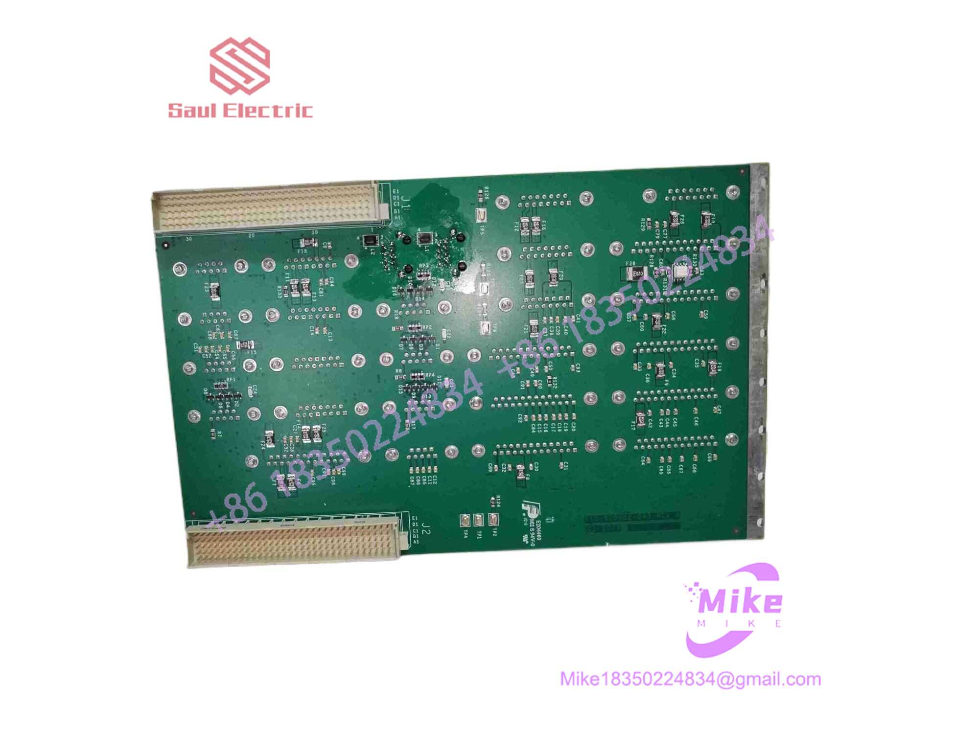
810-800082-043
Key Technical Specifications
| Parameter | Specification Detail |
| Manufacturer | Lam Research |
| Assembly Part Number | 810-800082-043 |
| Bus Architecture | VMEbus (IEEE-1014 standard) |
| Channel Density | 32-Channel High-Density Digital I/O |
| Isolation Type | Opto-isolated channels protecting internal logic |
| Form Factor | Standard VME Double-Eurocard PCBA |
| Hardware Addressing | Physical hex address switches / jumper blocks |
| Diagnostic Indicators | Multi-status LED array for channel state and bus traffic |
| Operating Environment | Cleanroom rack enclosure (15°C to 30°C) |
Global Sourcing & Live-Test SOP (Transparency Core)
Acquiring secondary-market VME electronics requires strict validation protocols to ensure zero hidden trace defects or component fatigue. Our sourcing workflow removes those risks through a rigorous testing lifecycle:
- Inbound Verification: Incoming circuit boards undergo microscopic optical checks to detect solder micro-cracks, trace corrosion, or heat stress around optocoupler banks. Original OEM laser markings are authenticated against asset databases.
- Live Simulation: We mount the card into a fully powered VME diagnostic rack configured to emulate active tool chassis loads.
- Diagnostics: Engineers cycle all 32 digital channels simultaneously using automated test scripts, verifying threshold switching speeds and optical isolation integrity with multi-channel logic analyzers. The board undergoes a continuous 24-hour heat run to flush out thermal drift anomalies.
- Final Prep: Once testing criteria are verified, the physical configuration jumpers are logged, and the unit is wrapped in conductive shielding material before vacuum-sealing in an ESD-safe moisture-barrier bag.
The Field Engineer’s Pitfall Guide
❗ Hex Address Configuration Errors: Failing to match the exact hardware address jumpers from the failed board to the replacement will cause the master CPU to throw a fatal bus error upon boot. Always copy the switch settings before installation.
❗ Hot-Plugging Rack Damage: Never insert or remove this VME module while the rack power supply is energized. I’ve seen technicians instantly fry input buffers and backplane bus drivers because they skipped powering down the card cage.
❗ Ignoring Field Wiring Voltage Ratings: Connecting high-voltage external power lines directly to low-voltage digital sense pins without proper intermediate relay isolation will instantly vaporize the board’s optocoupler channels. Double-check your terminal block mapping.
Intent-Driven FAQ
Can I hot-swap the 810-800082-043 module during tool maintenance?
No. VME architecture lacks hot-swap support. Always perform a complete system shutdown and cut rack power before replacing this digital I/O board.
Will replacing this card erase my tool’s operating system or software recipes?
No. This module functions strictly as a hardware I/O and interlock processor. All system software, configuration files, and process recipes reside on the master host hard drive and controller CPU.
How do I test if an interlock fault is caused by this board or the external sensor?
Check the onboard diagnostic LED array. If the channel LED remains dark when the external sensor trips, use a digital multimeter to verify that the physical voltage reaches the terminal connector pin before condemning the PCBA.
Are firmware chips socketed or surface-mounted on this version?
Most revisions utilize socketed microcontrollers or EPROMs. If a direct hardware swap requires matching an older system version, you can transfer the boot ROM from your legacy board if needed.
What kind of warranty coverage comes with this surplus module?
We provide a comprehensive one-year replacement warranty, covering any hardware or communication failure under normal cleanroom operating conditions.





