


Description
Lam 810-068158-014 | Etch System Control Board
Dynamic Product Introduction
Running an older etch bay means living under constant threat of sudden board-level lockups during a critical plasma step. When an I/O controller fails mid-wafer process, you aren’t just dealing with a simple hardware swap—you are burning thousands of dollars in ruined silicon and unbudgeted tool downtime. The Lam 810-068158-014 handles critical signal aggregation, interfacing chamber sensors, gas box mass flow controllers, and interlock lines back to the system processor with zero tolerance for signal drift.
Unlike standard industrial I/O cards, this specific PCB variant relies on hardened trace isolation and high-frequency noise filtering built to withstand the high-RF environment inside dry etch chambers. Upgrading to or stocking a verified 810-068158-014 eliminates the erratic interlock trips and bus timeout errors common to failing legacy revisions. Keeping a drop-in spare on hand is the cheapest insurance policy against unscheduled wafer aborts.
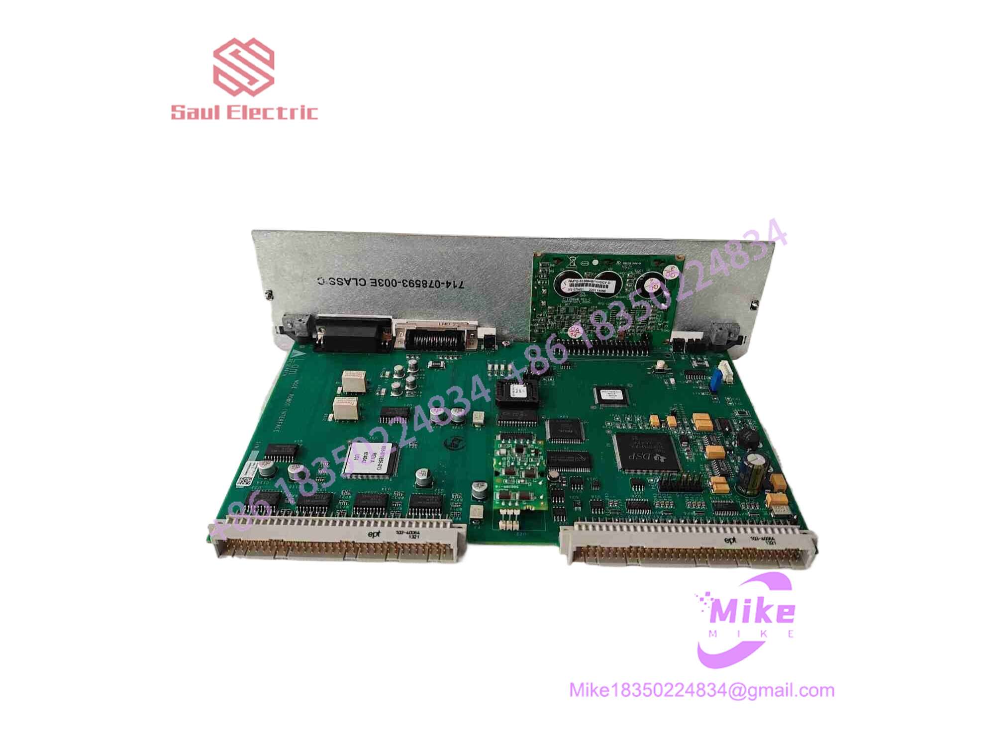
810-068158-014
Key Technical Specifications
| Parameter | Specification / Threshold |
| Part Number | 810-068158-014 |
| Manufacturer | Lam Research Corporation |
| Platform Compatibility | Lam Rainbow Series / Alliance Plasma Etchers |
| Operating Voltage | 24 VDC (Logic & I/O Power Rail) |
| Bus Interface | Multi-pin proprietary backplane edge connector |
| I/O Configuration | High-density mixed Digital I/O & Sensor Interface |
| Mounting Style | Rack-mount card cage insertion with retaining screws |
| Operating Temp Range | 10°C to 50°C (Ambient enclosure temperature) |
| Conformal Coating | Industrial-grade moisture and process-gas resistant coating |
| Status Indicators | On-board surface-mount diagnostic LEDs |
Global Sourcing & Live-Test SOP (Transparency Core)
Surplus semiconductor hardware requires far more than a basic continuity test. Every incoming Lam 810-068158-014 passes through our strict four-stage verification process before entering ready-to-ship inventory:
- Inbound Verification & Traceability:
- Visual inspection under magnification to detect cold solder joints, trace degradation, or swelling capacitors.
- Part number revision tracking, chip serial verification, and OEM label authenticating to prevent counterfeit insertion.
- Live Rack Simulation:
- Board insertion into a dedicated Lam test rack setup.
- Full backplane voltage stress test across the 24VDC logic rail under maximum load conditions.
- Signal & Protocol Diagnostics:
- Multi-channel digital I/O looping using calibrated test fixtures.
- Verification of signal response times and noise rejection using a Fluke scope across active relay outputs.
- Continuous 24-hour thermal soak inside an environmental chamber at 45°C to catch intermittent thermal drift components.
- Final Prep:
- Full diagnostic log generation tied to the board’s serial number.
- Thorough cleaning with isopropyl alcohol followed by anti-static conformal check and vacuum packaging in anti-static conductive shielding bags.
The Field Engineer’s Pitfall Guide
- ❗ Firmware and Hardware Revision Mismatches:
Never assume an
810-068158-014will automatically drop into a slot configured for an earlier revision (like an-002or-005) without checking system software levels. Inserting a higher revision board into an unpatched system motherboard can cause silent interlock failures—I once saw a fab team waste 14 hours troubleshooting a gas box interlock fault simply because the host software couldn’t map the revised register addresses of the new board. - ❗ Ignoring Backplane Stiffener Pins and ESD Precautions:
These cards feature high-density edge connectors with tiny ground pin contacts. Forcing the board into a warped backplane cage can bend outer pins or strip the gold plating off the edge fingers. Always back off the retention hardware, align the slide rails cleanly, and use a grounded wrist strap. A single ESD zap during hot installation can fry the onboard logic gates without leaving a single burn mark.
- ❗ Onboard DIP Switch and Jumper Blindness:
Do not pull the replacement board from the anti-static bag and slide it straight into the rack. Older Lam boards often have field-configurable jumper blocks or DIP switches for board address setting and termination resistance. Match every single jumper position on the new board to your pulled unit—otherwise, the system bus will hang during initialization, or worse, address two cards simultaneously.
Intent-Driven FAQ
Will swapping out the 810-068158-014 erase my system recipe parameters?
No. Recipe data and chamber calibration settings reside on the main host computer disk or system CPU board, not on this I/O interface board. However, swapping the board will reset active I/O communication states, so the tool must be in a complete, safe Standby or Maintenance mode before doing the swap.
Can I hot-swap this board while the etch system is powered on?
Absolutely not. Hot-swapping the 810-068158-014 risks pulling arc spikes across the backplane edge pins, which can fry adjacent cards or corrupt the host bus logic. Always power down the main chassis breaker and verify the card rack power rails are at zero volts before unseating the board.
What is the primary cause of failure on this specific board revision?
Thermal stress and capacitor degradation are the main culprits. Because these boards run inside dense card cages for years, local heat build-up gradually degrades electrolytic filter capacitors on the 24V rail. This leads to ripple voltage on logic lines, causing random signal glitches or dropped interlocks.
How do I verify if my existing 810-068158 board is repairable or dead?
Check the diagnostic status LEDs on the front edge of the card while under system power. If the power LED is dim or flickering, or if the board fails to respond during the system boot POST sequence, check the onboard surface-mount fuses with a multimeter. If fuses are intact but the board remains uncommunicative, the primary bus transceiver logic has likely suffered a breakdown.
What warranty coverage comes with these surplus or refurbished modules?
All fully tested and refurbished 810-068158-014 units ship with a standard 1-year replacement warranty. If the unit exhibits functional defects, communication drops, or I/O failure under normal operating parameters within 365 days of installation, it is eligible for an immediate advance replacement or full unit repair.





