


Description
Industrial Automation Part A.F.031.508 | New Surplus
Architect’s Product Breakdown
The component identified by part number A.F.031.508 operates as an integral hardware element within complex industrial automation and control infrastructures. Its primary responsibility is maintaining reliable signal transmission, power regulation, or logic communication across connected system nodes. Ensuring uncompromised performance from this module is essential to preventing data packet loss, loop degradation, or unexpected process shutdowns in continuous manufacturing environments.
Deploying or replacing this hardware requires strict adherence to system installation guidelines, proper grounding practices, and terminal torque specifications. Technicians must verify that all interface harnesses and backplane pins are free of debris or oxidation prior to seating the module to avoid high-resistance connection faults.
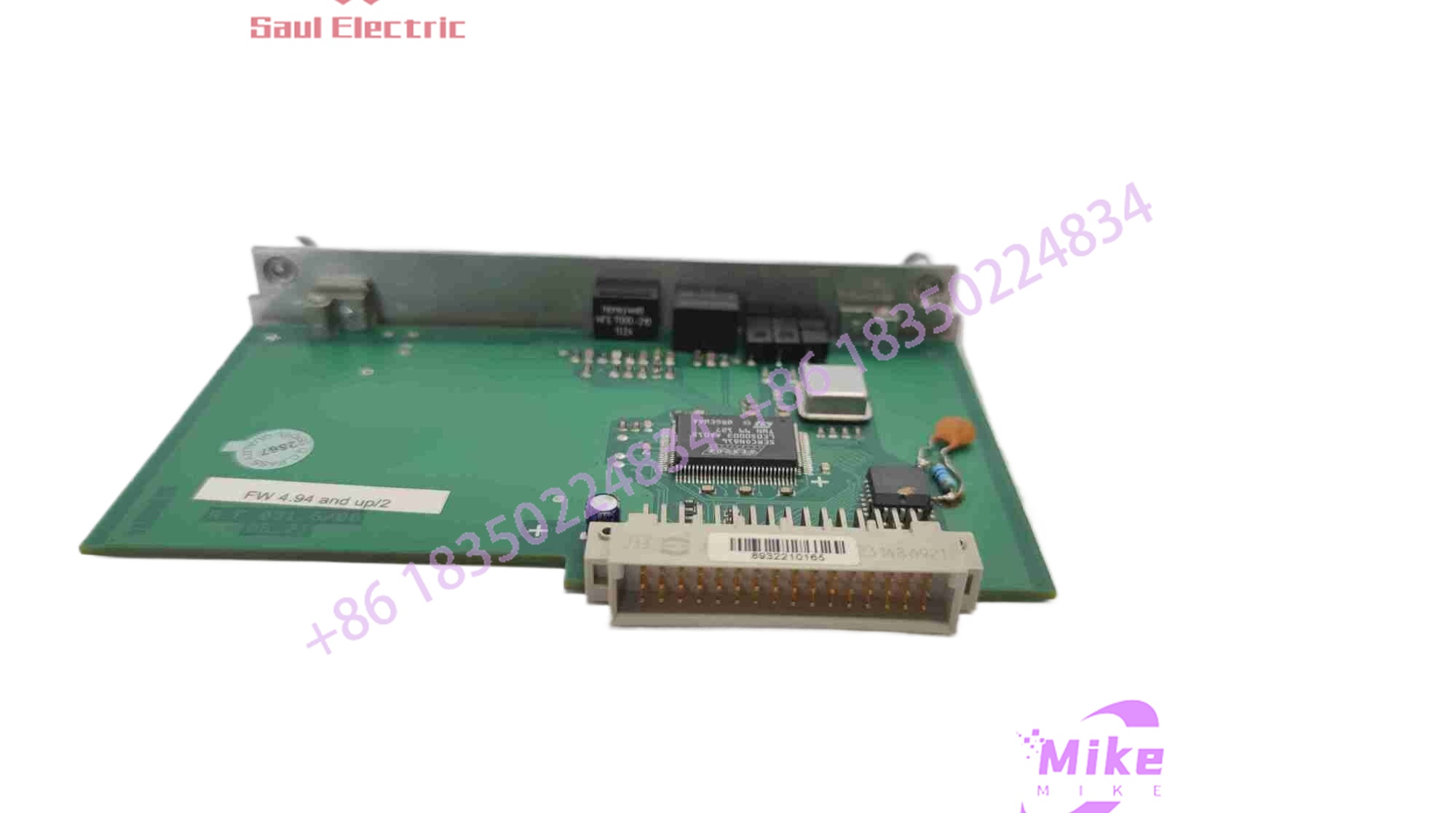
A.F.031.508
Key Technical Specifications
| Parameter | Specification |
|---|---|
| Part Number | A.F.031.508 |
| Module Type | Control / System Interface Module |
| Compatible Architecture | Industrial DCS / PLC / Automation Racks |
| Mounting Type | Chassis / DIN-Rail / Backplane Slot |
| Operating Temperature | 0°C to +60°C |
| Storage Temperature | -40°C to +85°C |
| Relative Humidity | 5% to 95% non-condensing |
Field Engineer’s Pitfall Guide (Unique Value)
- Backplane Pin Alignment: Forcing this module into a chassis slot or terminal base without proper alignment can bend delicate connector pins, resulting in intermittent electrical contact and difficult-to-diagnose communication dropouts.
- Shielding and Ground Disconnects: Failing to maintain a secure chassis ground connection across mounting plates introduces high-frequency electromagnetic interference, leading to erratic signal behavior.
- Static Discharge Vulnerability: Handling internal circuit boards or edge connectors without an ESD wrist strap in low-humidity environments can instantly damage sensitive solid-state components.
QA & Testing SOP (Transparency)
- Visual & Origin Verification: Units undergo microscopic inspection for authentic manufacturer stamps, solder joint integrity, and zero signs of physical stress or component wear.
- Test Bench Simulation: The module is inserted into a compatible test rig, undergoing continuous power-on cycles and signal verification loops to ensure thermal and operational stability.
- Signal Handshake Validation: Technicians verify response times, pinout continuity, and diagnostic indicators using calibrated bench equipment.
- Anti-Static Packaging: Post-testing, units are sealed inside moisture-barrier static-shielding bags complete with high-density protective foam padding.
Technical FAQ
- Can I hot-swap this module while the system is energized? No. Always de-energize and lock out the local power supply before extracting or inserting this component to prevent electrical arcing and backplane bus corruption.
- Does this unit require software configuration? Configuration parameters are typically managed by the primary system controller or node processor, though hardware jumpers or switch settings should always be verified against the replaced unit.
- What causes immediate communication or power faults after installation? This is typically driven by an incomplete seating of the edge connector, a loose wiring termination, or an unacknowledged hardware configuration mismatch.
- What warranty is provided with a surplus unit? Units carry a standard 12-month replacement warranty backed by comprehensive bench testing and quality assurance verification.





