


Description
Honeywell 381-639507-3 | TDC 3000 Connection Board Assembly
Dynamic Product Introduction
Field signal dropouts in legacy DCS installations frequently trace back to trace hairline fractures or connector pin oxidation on passive termination boards. The Honeywell 381-639507-3 connection board serves as the structural backbone for routing field inputs and outputs straight into Honeywell TDC 3000 High-Performance Process Manager (HPM) and APM processor racks.
Unlike active processing cards, this passive interconnection assembly handles high-density ribbon cable interfaces, providing galvanic separation pathways and organized bus routing across multiple field termination assemblies (FTAs). Installing a fully bench-audited 381-639507-3 unit eliminates intermittent open-circuit faults, restores solid backplane seat engagement, and ensures reliable signal handshakes across legacy Honeywell control nodes.
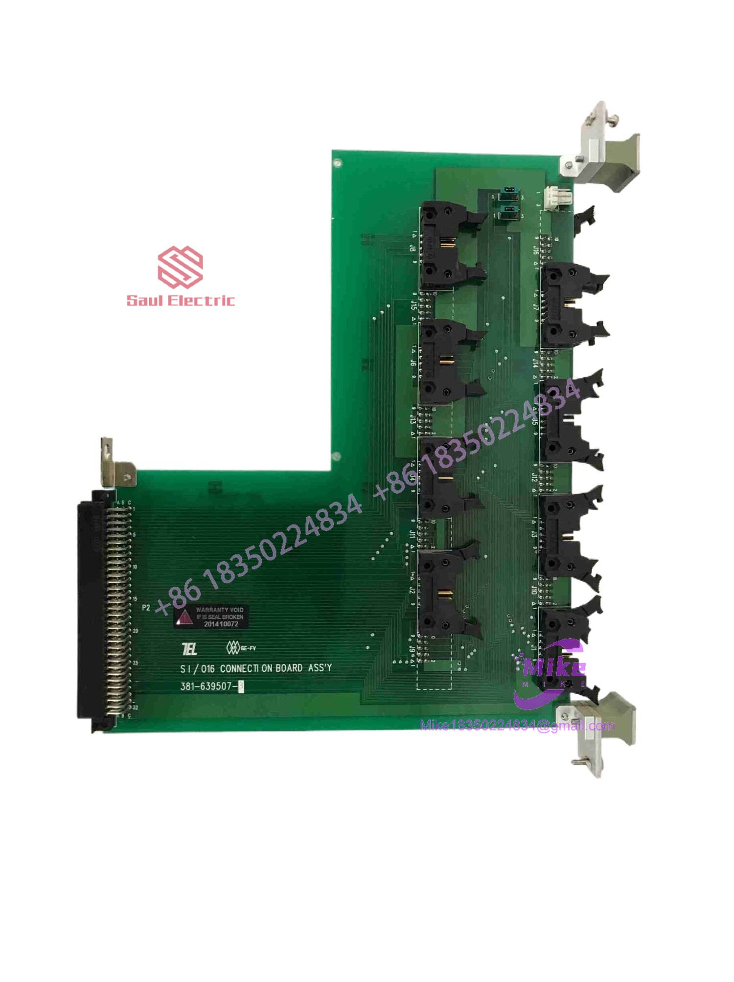
381-639507-3
Key Technical Specifications
| Parameter | Specification Detail |
| Part / Assembly Number | 381-639507-3 (Sub-Assembly: 51101620-100) |
| System Compatibility | Honeywell TDC 3000 / TPS DCS Racks |
| Associated Processor Modules | HPM (High-Performance Process Manager), APM, PM |
| Card Type | Interconnection / Termination Connection Board |
| Form Factor | Custom L-shaped / Multi-connector Honeywell DCS Board |
| Connection Interface | Multi-pin shrouded ribbon cable headers & card-edge backplane pins |
| Signal Handling | Analog and Digital I/O bus pass-through routing |
| Mounting Style | Rack-mount backplane slot retainer with card guides |
| Operating Temperature | 0°C to +60°C (32°F to 140°F) |
| Substrate Construction | Multi-layer flame-retardant FR-4 PCB with gold-plated contact pads |
Global Sourcing & Live-Test SOP (Transparency Core)
Legacy Honeywell DCS components are prone to pin corrosion, physical terminal cracking, or thermal degradation from decades of continuous panel service. Every incoming 381-639507-3 connection board undergoes a comprehensive quality control sequence before re-deployment:
Inbound Verification
- Microscopic inspection of gold card-edge fingers and multi-pin ribbon headers under high magnification to check for bent pins, corrosion, or trace lifting.
- Cross-referencing board fabrication numbers (
381-639507-3) and assembly silk-screen codes (51101620-100) against Honeywell engineering catalogs to verify OEM authenticity.
Live Simulation & Backplane Handshake
- The 381-639507-3 board is populated into an authentic Honeywell TDC 3000 test rack paired with active I/O processor cards.
- Multi-channel ribbon cables are mated to all header banks; loop continuity tests are executed across every pin to confirm zero trace resistance or open circuits.
Diagnostics & Burn-In
- High-density I/O signals are passed through the board while monitored via a digital multimeter to confirm line resistance specs match OEM baselines.
- The assembly undergoes a thermal cycle run at 50°C to stress passive board traces, solder joints, and multi-pin header contacts.
Final Prep
- Board contacts are cleaned using isopropyl solvent and treated with anti-oxidation contact preserver.
- The card is sealed inside static-shielding ESD bags with foam edge-protectors for secure transit.
The Field Engineer’s Pitfall Guide
❗ Mismatched Assembly Suffix Codes (51101620-100 vs. Alternate Revisions):
While the bare PCB board stamp reads 381-639507-3, the complete assembly number (often 51101620-100) dictates installed component jumpers and connector header populations. Swapping boards without matching the full assembly revision can leave specific field I/O channels unrouted to the front-end processor.
❗ Bent Header Pins During In-Cabinet Ribbon Mating:
The high-density multi-pin headers on the 381-639507-3 feature tight pin pitches. Inserting old, stiff ribbon cable connectors at an angle during hot-maintenance runs can easily bend or push back header pins—honestly, I’ve seen technicians lose an entire 16-channel analog input block simply because one corner pin bent sideways inside the shroud.
❗ Backplane Alignment Resistance:
Inserting this board into a legacy TDC 3000 card cage requires even pressure across both top and bottom card guides. Forcing the board when aligned improperly can shear off backplane alignment pins or crack the gold-plated edge contacts along the rear connector edge.
Intent-Driven FAQ
What is the relationship between part number 381-639507-3 and 51101620-100?
381-639507-3 represents the bare printed circuit board etching number, whereas 51101620-100 (or similar 511-series prefix) denotes the fully populated Honeywell board assembly including soldered headers, clips, and electronic components.
Does the 381-639507-3 board require software or firmware configuration?
No. The 381-639507-3 is a passive/hardwired signal connection board. It contains no onboard flash memory or programmable microcontrollers. All system node addresses and channel software configurations reside in the associated TDC 3000 processor cards.
Can I hot-swap this connection board while the DCS rack is powered?
While Honeywell TDC 3000 processors support specific hot-swap routines, disconnecting ribbon cables from the 381-639507-3 while active I/O loops are live can disrupt control loops or cause false channel alarms on your Operator Station. Always place associated I/O channels in Manual/Bypass prior to board service.
How do I troubleshoot intermittent signal drops on this board?
Check for oxidation on the card-edge fingers and verify ribbon cable latch tension on the front shrouded headers. Cleaning contacts with an electronics-grade cleaner and inspecting header pins with a jeweler’s loupe typically resolves intermittent connection faults.
What warranty coverage comes with refurbished or surplus units?
Every 381-639507-3 connection board shipped after passing our bench-testing SOP includes a full 1-year replacement warranty covering trace continuity, header pin integrity, and backplane contact functionality.





