

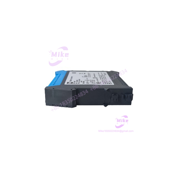
Description
GSI127 244-127-000-017-A2-B02 | VM600 Signal Isolator
Product Introduction
The Meggitt Vibro-Meter GSI127 244-127-000-017-A2-B02 is not a conventional signal isolator intended to sit anywhere in a generic 4–20 mA loop. It is a specialized galvanic separation unit for machinery vibration measurement, designed to preserve the measurement signal while electrically separating the sensor and monitoring sides.
Meggitt documentation specifically identifies 244-127-000-017 A2 B02 as a GSI127 used in VM600 measurement chains for piezoelectric sensors. The same documentation distinguishes the B02 configuration from B05, which is used for proximity-probe measurement chains. That suffix distinction matters when replacing a failed unit.
The GSI127 provides galvanic separation between the sensor side and monitor side, with published specifications indicating 4 kVRMS isolation and high rejection of rack/frame voltage interference. This helps prevent ground-loop problems and unwanted electrical noise from contaminating vibration measurements.

GSI127 244-127-000-017-A2-B02
Key Technical Specifications
- Model: GSI127
- Ordering Number: 244-127-000-017-A2-B02
- Manufacturer: Meggitt Vibro-Meter
- Device Category: Galvanic separation unit
- Primary Application: Vibration and machinery condition monitoring
- Sensor/Measurement Chain: Current-output vibration sensors and associated signal-conditioning chains
- Sensor-to-Monitor Isolation: 4 kVRMS
- Power Supply: 18–30 VDC
- Frequency Response: DC to 20 kHz
- Sensitivity: 1 V/mA ±1%
- Zero Point: 7 VDC ±200 mVDC
- Linearity: 0.2%
- Operating Temperature: -40 to +70°C
- Humidity: Up to 90% operating, non-condensing; up to 95% storage according to published secondary technical data
- Typical Weight: Approximately 0.15 kg
- Typical Application: VM600 vibration monitoring and machinery-protection systems
- A2-B02 Configuration: Documented for IPC/IVC-type measurement chains with the specified current-output interface.
Understanding the A2-B02 Suffix
Do not treat the suffix as cosmetic.
Published ordering information identifies:
- A2: explosive/hazardous-environment configuration
- B02: 1 V/mA sensitivity with a 12 mA nominal input corresponding to approximately 7 V output, for IPCxxx and IVCxxx applications
Meggitt’s own application documentation also shows A2-B02 and A2-B05 being selected for different sensor measurement chains within a VM600 installation.
That is why replacing an A2-B02 with another GSI127 variant purely because the housing looks identical can create a measurement-chain mismatch.
Global Sourcing & Live-Test SOP
For a surplus or refurbished 244-127-000-017-A2-B02, inspection should concentrate on the complete measurement chain rather than simply checking whether the module powers up.
- Nameplate verification: Confirm and the complete 244-127-000-017-A2-B02 ordering number.
- Variant verification: Record the A2 and B02 designations separately. Do not accept a generic as an equivalent without checking the application.
- Physical inspection: Examine the housing, terminals, mounting hardware, connector condition, and evidence of moisture or chemical contamination.
- Terminal inspection: Look for corrosion, damaged screw terminals, loose hardware, or evidence of previous rewiring.
- Power test: Apply a controlled 18–30 VDC supply and verify stable operation.
- Zero-point test: With the specified input condition, check that the output is consistent with the documented approximately 7 VDC zero point.
- Signal simulation: Use a calibrated current source to simulate the appropriate sensor/signal-conditioner output.
- Transfer test: Verify the expected 1 V/mA transfer relationship across the usable signal range.
- Linearity check: Compare measured output against calculated output at multiple test points rather than checking only one value.
- Frequency test: Where equipment is available, verify signal transmission over the required vibration-monitoring bandwidth.
- Isolation test: Perform insulation/isolation verification using an appropriate controlled test procedure and equipment. Do not improvise a high-voltage isolation test on a connected VM600 installation.
- Extended run: Operate the unit under representative signal conditions while monitoring output stability and temperature.
- Final record: Document input current, output voltage, test points, supply voltage, ambient temperature, serial/lot markings, and the exact A2-B02 configuration.
A particularly useful bench check is to simulate the expected current signal and confirm the corresponding voltage output. A unit that merely powers up has not demonstrated correct signal transfer.
Field Engineer’s Pitfall Guide
❗ 1. Do not substitute B02 and B05 without checking the sensor chain
The A2-B02 and A2-B05 variants appear together in Meggitt’s own VM600 application documentation, but they serve different measurement-chain applications. In one documented turbine configuration, A2-B02 units are used for piezoelectric sensors while A2-B05 units are used for proximity probes.
Match the complete part number to the existing sensor and signal-conditioning architecture.
❗ 2. Do not treat as a generic 4–20 mA isolator
The has a defined transfer characteristic and application-specific configuration. Published data for this exact B02 version identifies 1 V/mA ±1% sensitivity and a 7 VDC ±200 mVDC zero point.
If the existing system expects a different signal relationship, inserting the into the loop can produce an apparently plausible—but incorrect—measurement.
❗ 3. Verify the hazardous-area configuration before installation
The A2 designation is associated with the explosive/hazardous-environment configuration in published ordering information. That is not interchangeable with simply saying that the product is “industrial grade.”
For a hazardous-area installation, verify the actual certification documentation, installation method, associated sensor certification, wiring parameters, and barrier/isolation requirements for the complete circuit.
Intent-Driven FAQ
What is the Meggitt ?
The is a galvanic separation unit used in Vibro-Meter machinery vibration measurement systems. It electrically separates the sensor side from the monitoring electronics while transmitting the measurement signal.
What is the full part number?
The exact configuration discussed here is 244-127-000-017-A2-B02. The shorter designation identifies the product family; the complete ordering number identifies the specific configuration.
What does the B02 version do?
The B02 configuration is documented with 1 V/mA sensitivity and a nominal 12 mA input corresponding to approximately 7 VDC output, for IPCxxx and IVCxxx applications.
What is the isolation rating?
Published technical information specifies 4 kVRMS galvanic separation between the sensor side and monitoring side.
This should not be interpreted as permission to perform arbitrary high-voltage tests on an installed unit. The applicable safety procedure and certification documentation must govern any dielectric test.
What power supply does require?
Published specifications identify an 18–30 VDC supply range.
Verify the actual installation wiring before energizing a replacement.
What is the frequency range?
The published range is DC to 20 kHz, with 0.2% linearity reported in available technical data.
That bandwidth is relevant when the is used in machinery vibration measurement rather than simple low-speed process instrumentation.
Is used with ?
Yes. Meggitt application documentation specifically lists 244-127-000-017 A2 B02 as part of machinery-monitoring measurement chains.
Procurement Notes
The Meggitt Vibro-Meter 244-127-000-017-A2-B02 should be sourced as an exact-configured machinery-monitoring component, not as a generic signal isolation module.





