


Description
Giddings & Lewis 502-03944-00 | In-Stock Field Replacement Board
Dynamic Product Introduction
Axis drift or communication timeouts on a heavy-duty Giddings & Lewis horizontal boring mill or machining center almost always track back to thermal fatigue on primary rack interface cards. The Giddings & Lewis 502-03944-00 (board code M.1016.9428R13) acts as a critical signal distribution node within legacy PiC900 and CNC controller chassis.
Designed to handle high-speed feedback routing and backplane power regulation, this board isolates field noise from primary CPU processing logic. Installing a fully bench-audited 502-03944-00 module restores tight axis control, eliminates intermittent bus synchronization faults, and extends the operational lifespan of your high-value G&L machine tools without requiring a complete control system retrofit.
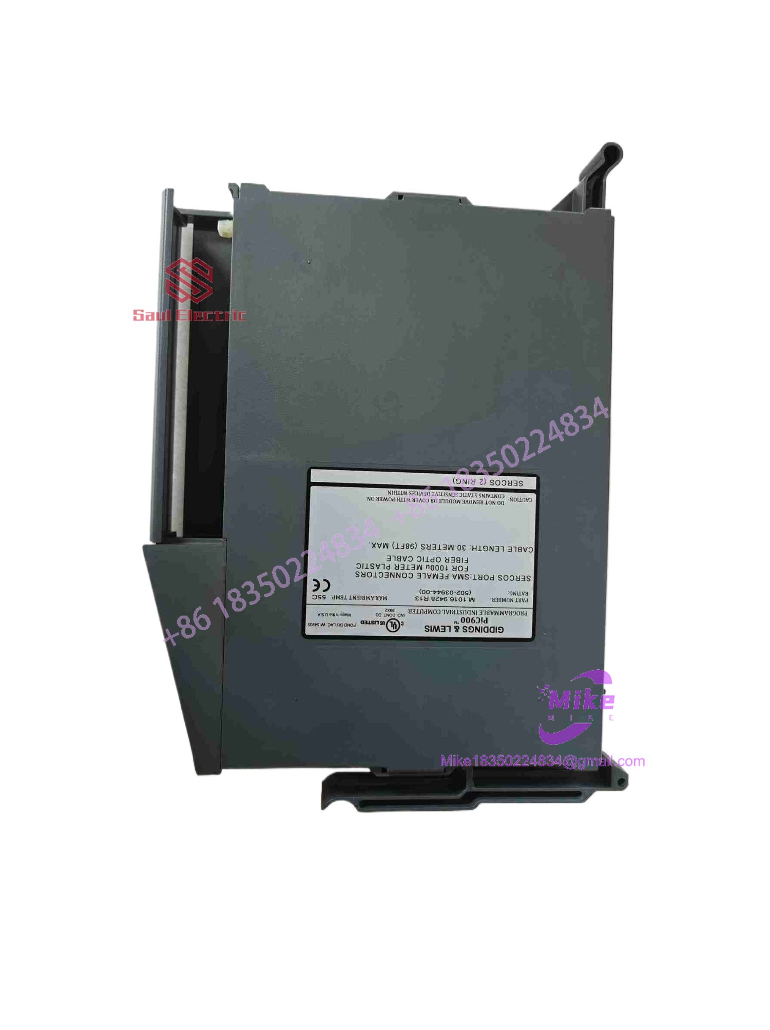
502-03944-00 M.1016.9428R13
Key Technical Specifications
| Parameter | Specification Detail |
| Part / Catalog Number | 502-03944-00 |
| PCB Stamping / Artwork Code | M.1016.9428R13 |
| OEM Manufacturer | Giddings & Lewis (G&L Motion Control) |
| System Compatibility | G&L PiC900, PiC90, and legacy CNC controller racks |
| Module Type | Interface / Signal Distribution Board Assembly |
| Bus Interface | Proprietary G&L backplane card-edge connectors |
| Power Input | Drawn from rack backplane (+5 VDC, ±12 VDC / 24 VDC rails) |
| Operating Temperature | 0°C to +55°C (32°F to 131°F) |
| Substrate / Construction | Heavy-duty FR-4 PCB with gold-plated contact fingers |
Global Sourcing & Live-Test SOP (Transparency Core)
Deploying legacy CNC hardware into active production lines demands rigorous testing to prevent unexpected machine downtime. Here is our bench validation workflow for every incoming 502-03944-00 board:
Inbound Verification
- Microscopic inspection of gold card-edge fingers, solder joints, and traces for hairline fractures, thermal darkening, or mechanical wear.
- Verification of base part number (
502-03944-00) and board revision marking (M.1016.9428R13) against G&L factory documentation.
Live Rack Bench Simulation
- The module is inserted into an authentic Giddings & Lewis controller rack paired with active CPU and servo interface modules.
- Signal continuity across all backplane pins and onboard routing paths is verified using precision logic analyzers.
Load Diagnostics & Burn-In
- Simulated multi-axis motion cycles are run continuously to stress power rails and signal paths on the board.
- A 24-hour heat-soak run at 50°C ensures passive components and trace junctions remain stable under continuous operational loads.
Final Prep
- Edge contacts are solvent-cleaned and treated with an anti-oxidation protective coating.
- Sealed inside anti-static ESD shielding prior to dispatch.
The Field Engineer’s Pitfall Guide
❗ Confusing Revision Suffixes (M.1016.9428R13 vs. Earlier Revisions):
While the bare PCB etching reads 502-03944-00, the R13 revision level designates specific component populations and trace updates. Substituting an earlier revision (e.g., R10 or R11) into a rack expecting the R13 build can result in unassigned pinouts or bus timing mismatches.
❗ Card Alignment Resistance in Legacy Racks:
G&L card cages rely on tight card-guide tolerances. Forcing the board into the slot without proper alignment can lift gold contacts off the rear connector edge—honestly, I’ve seen technicians ruin a replacement card in seconds simply by forcing a misaligned module into an aging rack.
❗ Neglecting Rack Power Supply Ripple:
System interface boards often fail prematurely due to high voltage ripple from aging rack power supplies. Always verify that your controller’s 5 VDC and 24 VDC power rails are clean and within a ±2% voltage window before installing a replacement module.
Intent-Driven FAQ
What is the difference between part number 502-03944-00 and M.1016.9428R13?
502-03944-00 is the primary Giddings & Lewis ordering part number, while M.1016.9428R13 represents the underlying PCB artwork and component revision code stamped directly on the board.
Does the 502-03944-00 board require software parameter downloading?
No. This module functions as a hardware interface and bus distribution card. It does not store user logic or CNC parameter files; all software configuration resides in the main system CPU.
Can I hot-swap this card while the G&L rack is energized?
No. Power to the rack must be completely isolated before removing or installing the 502-03944-00 card to prevent electrical arcing across the backplane edge contacts.
What causes signal loss on these legacy G&L interface cards?
Oxidation on gold edge contacts, thermal stress on bus buffer chips, and vibration-induced micro-cracks in solder joints are the most common causes of intermittent signal loss in older machine tool cabinets.
What warranty coverage is included with surplus or refurbished units?
Every Giddings & Lewis 502-03944-00 module passing through our testing facility includes a full 1-year replacement warranty covering trace continuity, contact integrity, and operational bus stability.





