

Description
GESPAC GESMEM-12D | Industrial Memory PCB Module
Product Introduction
The GESPAC GESMEM-12D is a legacy industrial memory PCB intended for use within GESPAC control-system hardware. This is a board-level component, not a standalone PLC and not a field I/O module. GESPAC component references list the GESMEM-12D as a memory board, alongside CPU, serial I/O, disk-controller, analog, digital I/O, and backplane assemblies in the same control-system architecture.
That distinction matters during replacement. A memory board can be electrically functional and still be the wrong revision or population for a particular controller configuration. Available records identify the GESMEM-12D as a “Memory, Unpopulated” assembly, while other equipment records describe the MEM-12D as a PCB assembly. Therefore, the actual component population on the board should be inspected before assuming that every GESMEM-12D carries identical RAM/EPROM devices.
For legacy GESPAC equipment, preserving the original memory architecture can be more practical than attempting an undocumented modernization. If the existing controller is still operational, photograph and record the board population, jumper configuration, revision markings, and installed memory devices before removing the original board.
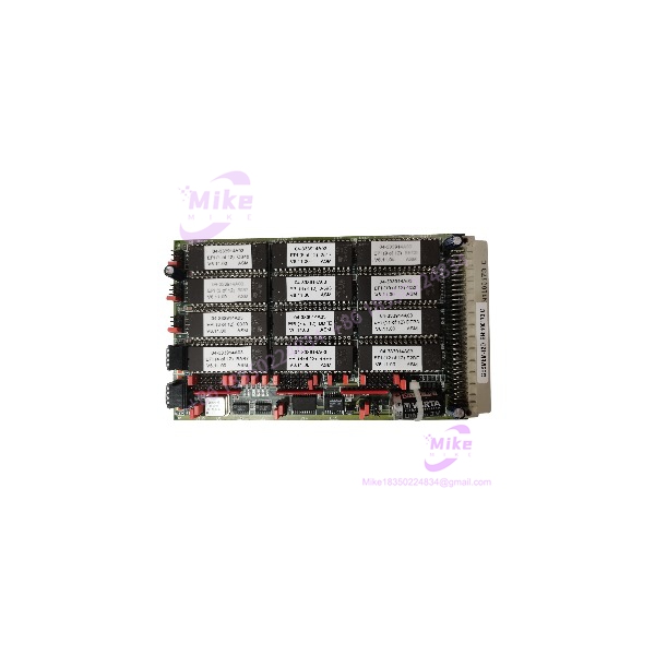
GESMEM-12D
Key Technical Specifications
- Manufacturer: GESPAC
- Model: GESMEM-12D
- Alternate Model Formatting: GESMEM12D
- Board Designation: MEM-12D
- Product Category: Industrial control-system memory PCB
- Functional Category: RAM / memory board
- Known Description: Memory, unpopulated
- Board Assembly Reference: GESMEM12BC-RAM/EPROM is associated with MEM-12D records
- Installation Type: Plug-in industrial control-system circuit board
- System Architecture: GESPAC modular control-system hardware
- Typical System Relationship: Used alongside GESPAC CPU, I/O, communications, disk-controller, and backplane boards
- Lifecycle: Legacy / obsolete equipment
Available component references place the in the same GESPAC hardware ecosystem as the GESBUS-20A 20-slot backplane, GESSBS-41-series CPU boards, GESSIO serial I/O, GESADC analog input, and GESCIO digital I/O assemblies. This establishes its role as part of a modular control architecture rather than an independent controller.
What Is Not Reliably Documented
Publicly accessible records do not provide enough authoritative information to state the exact memory capacity, memory-device type, address map, bus timing, jumper assignments, or electrical limits for every revision.
That is intentional in this listing. Do not assume a particular RAM or EPROM capacity from the model number alone. The physical board population and revision should be checked against the host GESPAC controller before procurement.
Global Sourcing & Live-Test SOP
Because the is an obsolete board-level component, incoming inspection deserves more attention than a normal catalog replacement.
1. Inbound Verification
Record the following before powering the board:
- Exact marking
- MEM-12D designation where present
- PCB revision and date codes
- Serial number or assembly number
- Memory-device manufacturer and markings
- RAM/EPROM population
- Socket condition
- Jumper or DIP-switch positions
- Connector condition
- Evidence of corrosion or previous rework
Photograph both sides of the PCB. For a legacy memory board, those photographs become part of the procurement record and can be extremely useful when comparing replacement inventory later.
2. Component-Level Inspection
Inspect the memory sockets and solder joints closely.
Look for:
- Oxidized IC pins
- Bent socket contacts
- Cracked solder joints
- Missing ICs
- Incorrectly installed memory devices
- Damaged edge connectors
- Flux residue from previous repair
- Corrosion around older socketed devices
- Evidence of component substitution
A board described as “unpopulated” should not automatically be treated as a complete functional replacement. Confirm which components are physically installed on the actual unit being purchased.
3. Controller Compatibility Test
The safest test environment is the original GESPAC controller or an approved equivalent system.
Before insertion:
- Power down the host system according to its service procedure.
- Record the original memory-board position.
- Compare connector keying and board dimensions.
- Verify the replacement’s revision and component population.
- Confirm all jumper/DIP settings against the known-good board.
- Install the .
- Perform the controller’s normal startup and memory-detection sequence.
- Verify that the controller reaches its expected operating state.
Do not perform blind hot-swapping. The absence of a published hot-swap specification means the should be treated as a power-off installation unless the host-system documentation explicitly states otherwise.
4. Functional Verification
A useful acceptance test should verify more than whether the CPU simply boots.
Where the system permits:
- Execute the controller’s memory diagnostic.
- Perform repeated cold starts.
- Perform controlled warm restarts.
- Verify program retention.
- Verify process-data retention where applicable.
- Check diagnostic messages.
- Compare memory-related startup behavior with the original board.
- Monitor the system for intermittent memory faults during an extended run.
For a legacy controller, intermittent socket contact can produce symptoms that initially resemble CPU or backplane faults. If the controller behaves inconsistently, inspect the memory-board sockets and edge connector before replacing the CPU.
5. Final QC Documentation
Record:
- model
- PCB revision
- Installed memory devices
- Jumper/DIP configuration
- Controller tested with
- Diagnostic result
- Cold-start result
- Warm-restart result
- Program-retention result
- Visual condition
- Test date
Package the board in an ESD-safe bag with rigid mechanical protection around the PCB and edge connector.
Field Engineer’s Pitfall Guide
❗ Warning 1 — Do Not Assume Every Has the Same Memory Population
This is the biggest sourcing issue.
GESPAC references describe the as “Memory, Unpopulated,” while other records identify populated MEM-12D PCB assemblies.
Consequently, compare the actual IC population and PCB revision with the installed board. A visually similar board can have a materially different configuration.





