


Description
FANUC A860-2109-T302 | Pulse Codder Encoder, New Surplus
Architect’s Product Breakdown
The FANUC A860-2109-T302 functions as the critical sensory feedback node for industrial AC servo motors. Mounted directly to the rear shaft extension of the motor housing, this optical pulse codder reads precision-etched glass or metal encoder discs to translate mechanical rotation into high-speed digital feedback pulses. These signals are piped back to the servo amplifier and master CNC controller to close the velocity and position loops, ensuring nanometer-scale path precision and synchronization during complex multi-axis machining operations.
Deploying or replacing an encoder requires extreme adherence to mechanical alignment and cleanroom-level contamination control. Because internal optical tracks and photodiodes operate with microscopic tolerances, introducing oil, grease, or dust during installation permanently ruins the feedback signal. When swapping a unit, technicians must ensure the shaft taper or straight-shaft coupling is seated true to prevent runout vibration, which rapidly degrades bearing life and triggers erratic encoder communication alarms.
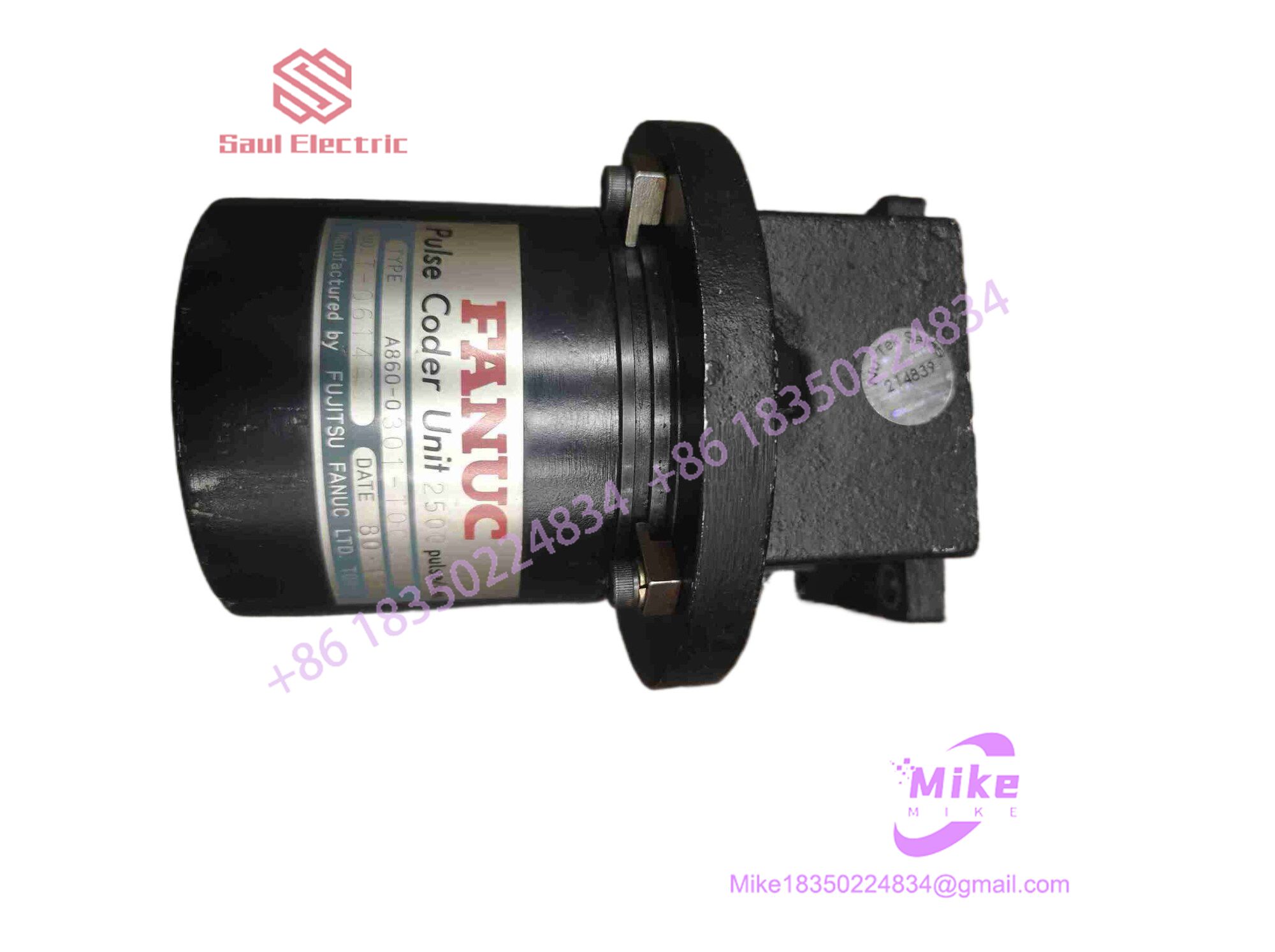
A860-2109-T302
Key Technical Specifications
| Parameter | Specification |
| Manufacturer | FANUC |
| Part Number | A860-2109-T302 |
| Series | FANUC A860 Pulse Codder / Position Coder |
| Device Type | Optical Rotary Servo Encoder |
| Maximum RPM | Up to 10,000 RPM |
| Mounting Interface | 68mm Standard Servo Flange |
| Cooling Method | Natural Convection / Motor Enclosure Conduction |
| Operating Temperature | 0°C to 60°C (Standard Industrial Limits) |
Field Engineer’s Pitfall Guide
- Electrostatic Discharge (ESD) and Optical Contamination: Warning: Never touch the exposed internal circuit board or optical disk components. Always wear an ESD grounding strap and keep protective covers in place until final mechanical mating in a clean environment.
- Forcing Shaft Alignment: Do not hammer or force the encoder hub onto the motor shaft. I have seen maintenance techs shatter internal glass code discs instantly by tapping the encoder housing with a mallet during installation. Always slide it on smoothly and torque clamping screws evenly.
- Ignoring Cable Shield Grounding: Failing to maintain continuous 360-degree shield grounding on the encoder feedback cable invites severe electrical noise interference from high-frequency PWM servo motor leads, causing intermittent feedback loss or “Pulse Coder Disconnected” alarms.
QA & Testing SOP (Transparency)
- Visual & Structural Audit: Incoming encoders are inspected under optical magnification for housing cracks, connector pin integrity, shaft runout, and authentic OEM labeling.
- Static Bench & Electrical Check: Technicians verify internal power rail resistance, signal isolation, and logic supply continuity across connector pins.
- Dynamic Motor Test Bench Rig: The encoder is mounted onto a verified FANUC test motor running on a live servo amplifier rack to evaluate high-speed pulse tracking up to maximum rated RPM.
- Thermal Drift & Signal Stability Run: Units undergo a prolonged operational burn-in cycle to ensure signal phase shift stability and thermal equilibrium prior to anti-static vacuum sealing.
Technical FAQ
Can the A860-2109-T302 encoder be repaired at the component level if the internal disk is damaged?
No. Due to the microscopic tolerances of the optical tracks and alignment precision required, field-level repairs or disk replacements are impossible. Full unit exchange or certified depot rebuilding is standard industry practice.
What causes an Alarm 300 or pulse coder fault on the CNC controller after installation?
This typically points to an improper electrical connection, damaged feedback cable shielding, or an unseated connector plug. Check continuity across all signal pairs and verify shield grounding.
Does replacing this encoder require axis re-mastering or zero-point return?
Yes. Because swapping a motor encoder changes the absolute position reference relative to the machine home switches, you must perform a complete axis re-mastering and zero-return procedure after installation.
Are replacement connector plugs available separately?
Yes, matched military-spec or proprietary plug housings can be sourced separately, but ensuring proper solder cup insulation and strain relief is vital to prevent short circuits.





