


Description
FACTS F4-16DA-1 | 12-Bit 4-20mA Current Output Module
Dynamic Product Introduction
A control valve that receives the wrong current signal does not always fail immediately. It may drift, respond slowly, or move to an incorrect operating point while the PLC logic appears completely normal. That is why analog output modules require the same attention as CPUs and communication cards.
The FACTS Engineering F4-16DA-1 is a high-density analog output module designed for the DirectLogic DL405 PLC platform. It provides 16 single-ended 4–20 mA current outputs with 12-bit digital-to-analog conversion, allowing PLC programs to regulate process devices such as control valves, variable-speed drives, positioners, and industrial transmitters.
Compared with lower-channel analog output cards, the F4-16DA-1 focuses on reducing rack expansion while maintaining individual current-loop control. Sixteen output channels from one PLC slot can simplify cabinet layouts where multiple analog actuators are required.
In field deployments, the difficult part is rarely installing the card. The real challenge is matching loop power, load resistance, scaling values, and channel addressing. A module can pass a basic bench test while still producing incorrect field behavior if the current loops are wired incorrectly.
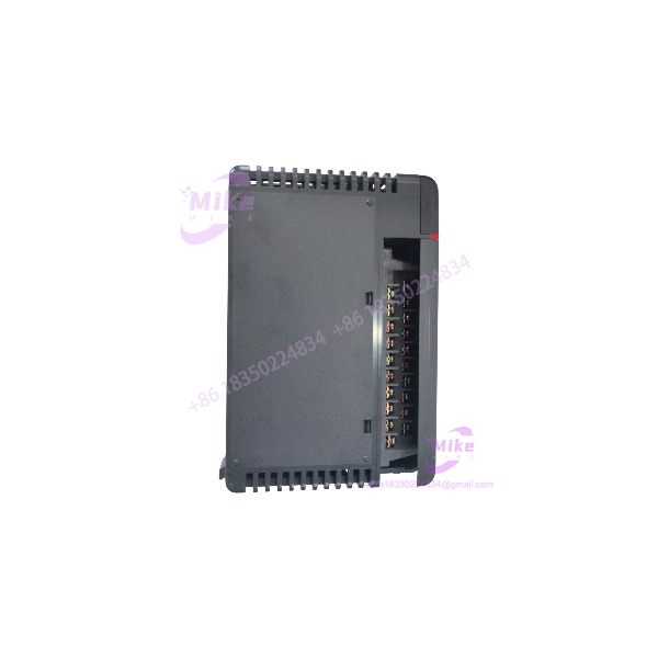
F4-16DA-1
Key Technical Specifications
- Model: F4-16DA-1
- Manufacturer: FACTS Engineering
- PLC Platform: DirectLogic DL405
- Module Type: Analog current output module
- Output Channels: 16 channels
- Signal Type: 4–20 mA current output
- Output Configuration: Single-ended, one common
- Resolution: 12-bit
- Digital Conversion Range: 1–4095 counts
- Output Type: Sinking current output
- Isolation: Non-isolated channels
- External Power Supply: 21.6–26.4 VDC
- Recommended External Supply: 24 VDC
- Maximum Loop Supply: Up to 48 VDC with suitable load resistance
- Load Resistance Range:
- 0–480 Ω at 18 VDC
- 220–740 Ω at 24 VDC
- 1550–1760 Ω at 48 VDC
- Conversion Time:
- Full-scale change: approximately 400 µs
- Digital-to-output update: approximately 2.25–4.5 ms
- Base Power Consumption: Approximately 90 mA at 5 VDC
- External Current Requirement: 100 mA + approximately 20 mA per active current loop
- Operating Temperature: 0°C to 60°C
- Installation: DL405 local, expansion, or remote I/O configuration
- Programming Software: DirectSOFT v4.0 or later
The F4-16DA-1 is specifically a current-output module. It should not be confused with the F4-16DA-2, which provides voltage outputs. The two modules share the same family name but serve different field devices and wiring methods.
Global Sourcing & Live-Test SOP
For surplus FACTS Engineering F4-16DA-1 inventory, confirming that the module powers up is only the first checkpoint.
Analog output failures are often subtle. A damaged DAC channel, unstable loop driver, or incorrect current scaling can remain hidden until the field device reacts incorrectly.
Inbound Verification
Every incoming F4-16DA-1 should receive:
- Exact model verification
- Serial number recording
- Physical condition inspection
- Terminal block inspection
- Connector inspection
- Storage-condition review
Inspect carefully:
- Terminal corrosion
- Cracked removable terminal blocks
- PCB contamination
- Heat discoloration
- Damaged mounting clips
- Signs of previous overcurrent events
Confirm the model suffix.
The difference between:
- F4-16DA-1: 16-channel 4–20 mA output
- F4-16DA-2: 16-channel voltage output
is not a software setting. The output electronics are different.
Live Simulation
A proper validation requires a compatible DL405 PLC rack.
Recommended procedure:
- Install the F4-16DA-1 in a verified DL405 base.
- Confirm PLC recognition.
- Connect external 24 VDC supply.
- Configure output addressing.
- Connect calibrated current measurement equipment.
Test output points:
- Channel 1 at 4 mA
- Channel 1 at 12 mA
- Channel 1 at 20 mA
- Repeat across all channels
Verify:
- Current accuracy
- Channel addressing
- Output stability
- Response during value changes
A single tested channel does not prove a sixteen-channel module is healthy.
Diagnostics
Recommended equipment:
- Fluke multimeter with current measurement capability
- Precision loop load
- 24 VDC regulated supply
- DL405 programming environment
Test sequence:
- Command minimum output.
- Verify approximately 4 mA.
- Command mid-scale output.
- Verify approximately 12 mA.
- Command full-scale output.
- Verify approximately 20 mA.
- Check output stability under load.
The F4-16DA-1 uses external loop power, so incorrect power wiring can create false module failures. The output stage sinks current from the external supply rather than generating an isolated powered loop.
Perform:
- Power-cycle testing
- Extended output operation
- Multiple-channel simultaneous testing
- Thermal observation under load
Final Preparation
Before shipment:
- Record tested channels.
- Record measured current values.
- Document external power test conditions.
- Protect terminal connections.
- Apply ESD-safe packaging.
- Maintain serial traceability.
For industrial replacement stock, a tested analog output card should include evidence that the DAC channels were exercised—not only that the PLC rack powered on.
The Field Engineer’s Pitfall Guide
❗ Do not replace the F4-16DA-1 with a voltage-output module.
The F4-16DA-1 outputs 4–20 mA current signals, while similar-looking modules may output voltage ranges such as 0–10 VDC. Connecting a current-output module where a voltage signal is expected can damage equipment or create incorrect control behavior. I have seen actuator problems traced back to a simple analog-output family mismatch.
❗ Do not ignore external loop power requirements.
The F4-16DA-1 requires a 24 VDC external supply for current-loop operation. Without proper loop power and load resistance calculation, technicians may measure unstable current and incorrectly blame the PLC module.
❗ Do not forget channel addressing after replacement.
analog modules use PLC output data mapping and channel selection logic. A replacement module may physically work while every field device receives the wrong output channel if the addressing configuration is not restored correctly.
Intent-Driven FAQ
What is the FACTS Engineering F4-16DA-1 used for?
The F4-16DA-1 is a DirectLogic analog output module used to generate sixteen 4–20 mA current signals for industrial control devices.
How many analog outputs does the F4-16DA-1 provide?
The module provides 16 analog current output channels with 12-bit resolution.
Does the F4-16DA-1 output 0–10 VDC?
No. The F4-16DA-1 is a 4–20 mA current output module. The voltage-output equivalent belongs to the F4-16DA-2 family.
Does the F4-16DA-1 require external power?
Yes. The module requires an external 24 VDC supply for current-loop operation. The available loop resistance depends on supply voltage and field load conditions.
Can I hot-swap the F4-16DA-1?
No. Treat it as a PLC rack component. Remove and install the module only after proper power isolation and according to site procedures.
How should a used F4-16DA-1 be tested before installation?
A proper test should include:
- All 16 channels
- 4 mA output verification
- 12 mA midpoint verification
- 20 mA full-scale verification
- External loop power test
- Load resistance check
- PLC communication/address verification
What causes incorrect F4-16DA-1 output signals?
Common causes include:
- Wrong channel addressing
- Incorrect scaling values
- Missing loop power
- Excessive load resistance
- Wiring polarity errors
- Failed output driver channel
Procurement verdict: The FACTS Engineering F4-16DA-1 remains a practical solution for maintaining legacy DirectLogic installations requiring dense analog current control. Its main strengths are 16-channel capacity, 12-bit resolution, and 4–20 mA compatibility.
For replacement sourcing, verify the complete application: F4-16DA-1 model, rack compatibility, external 24 VDC loop supply, load resistance, channel mapping, and actual output testing. Matching the part number is only the beginning; matching the control loop is what keeps the process stable.





