


Description
FACTS F4-16AD-2 | DL405 16-Channel Analog Input Module
Dynamic Product Introduction
Analog troubleshooting becomes expensive when every transmitter check requires stopping production. A failed input module can look like a sensor problem, a wiring fault, or even a PLC logic issue. The FACTS Engineering F4-16AD-2 removes some of that uncertainty by providing sixteen dedicated analog voltage acquisition channels inside the DL405 PLC ecosystem.
The F4-16AD-2 is a 16-channel analog input module designed for DirectLogic 405 systems. It accepts 0–5 VDC and 0–10 VDC single-ended voltage signals and converts them into 12-bit digital data values for PLC processing. The module supports reading all sixteen analog channels within one CPU scan on compatible D4-440 and D4-450 CPUs.
Compared with smaller analog input cards, the F4-16AD-2 focuses on channel density. Sixteen inputs from one slot can reduce cabinet expansion requirements when monitoring multiple transmitters, pressure sensors, temperature transmitters with voltage outputs, or machine feedback devices.
In field deployments, the most common failure is not the conversion electronics itself. It is incorrect scaling, shared common wiring mistakes, or installing a module without checking the PLC power budget (especially in older DL405 racks).
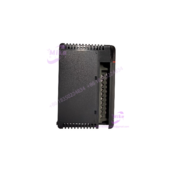
F4-16AD-2
Key Technical Specifications
- Model: F4-16AD-2
- Manufacturer: FACTS Engineering
- PLC Platform: DirectLogic DL405
- Module Type: Analog voltage input module
- Number of Channels: 16 single-ended inputs
- Input Signal Range: 0–5 VDC, 0–10 VDC
- Resolution: 12-bit (1 in 4096 counts)
- Input Configuration: Single common terminal
- Input Isolation: Analog inputs optically isolated from PLC logic components
- Input Impedance: Minimum 100 kΩ (datasheet specification varies by documentation revision)
- Conversion Time: 0.4 ms per channel
- CPU Scan Update: Up to 16 channels per scan on supported CPUs
- Linearity Error: ±2 counts maximum
- Input Stability: ±1 count
- Filtering: Low-pass filtering, approximately 20 Hz cutoff
- External Power Supply: 21.6–26.4 VDC
- Module Power Requirement: Approximately 75–80 mA from PLC base supply
- Terminal Block: Removable terminal block
- Operating Temperature: 0°C to 60°C
- Storage Temperature: -20°C to 70°C
- Installation: Any compatible DL405 local, expansion, or remote I/O slot
- Required Discrete I/O Points: 16 input points
The F4-16AD-2 is specifically a voltage input module. It should not be treated as a universal analog card. Signal type, transmitter output range, grounding method, and scaling configuration must match the PLC application.
Global Sourcing & Live-Test SOP
For surplus FACTS Engineering F4-16AD-2 inventory, a visual inspection is only the first screening step.
Analog modules often fail silently. A damaged input channel may still allow the PLC rack to start while producing incorrect engineering values.
Inbound Verification
Each incoming F4-16AD-2 should receive:
- Exact model verification
- Serial number recording
- Physical inspection
- Terminal block inspection
- Connector inspection
- Housing inspection
- Storage-condition review
Inspect for:
- Cracked terminal blocks
- Oxidized contacts
- Burn marks near power terminals
- Damaged PCB housing
- Evidence of moisture exposure
Confirm the module identity before testing. Similar DL405 analog modules may have different input types, channel counts, or signal ranges.
Live Simulation
A proper validation setup should use a compatible rack.
Test procedure:
- Install the F4-16AD-2 into a verified compatible base.
- Apply required PLC rack power.
- Connect external 24 VDC supply if required.
- Configure the PLC address allocation.
- Apply calibrated analog voltage signals.
Recommended input simulation:
- Channel 1: 0 VDC
- Channel 2: 5 VDC
- Channel 3: 10 VDC
- Remaining channels: stepped voltage values
Verify:
- Raw digital counts
- Channel addressing
- Conversion stability
- Scaling behavior
A module that reads correctly on one channel is not automatically healthy. All sixteen channels should be exercised.
Diagnostics
Recommended test equipment:
- Calibrated voltage source
- Fluke multimeter
- PLC programming software
- Controlled DC supply
Verification steps:
- Measure 0–10 VDC accuracy.
- Check zero offset.
- Check full-scale reading.
- Confirm repeatability.
- Perform power cycling.
- Monitor analog values during extended operation.
The F4-16AD-2 specification lists 12-bit resolution, meaning the full input range is divided into 4096 digital counts. Small offset errors can become noticeable when the application uses tight engineering tolerances.
Final Preparation
Before shipment:
- Record tested channel count.
- Document measured input performance.
- Record physical condition.
- Protect removable terminal block.
- Apply ESD-safe packaging.
For industrial replacement inventory, the test report matters. A used analog module without channel verification creates unnecessary commissioning risk.
The Field Engineer’s Pitfall Guide
❗ Do not assume every analog module is interchangeable.
The F4-16AD-2 is a voltage input module supporting 0–5 VDC and 0–10 VDC signals. Replacing it with a current-input or mixed-signal module can create incorrect scaling and unexpected PLC values. I have seen plants replace analog cards based only on slot compatibility and later discover every transmitter reading was wrong.
❗ Do not ignore common-terminal wiring.
The F4-16AD-2 uses a single-ended input arrangement with shared common reference. Incorrect transmitter grounding or shield termination can introduce unstable readings, especially with long field cables.
❗ Do not exceed the rack power budget.
Adding multiple analog modules increases the load on the PLC power supply. The F4-16AD-2 requires consideration of both PLC base power availability and available discrete I/O resources. I’ve seen older racks fail only after expansion because the original power calculations were never updated.
Intent-Driven FAQ
What is the FACTS Engineering F4-16AD-2 used for?
The F4-16AD-2 is a 16-channel analog input module used with DirectLogic PLC systems. It converts voltage-based field signals into digital values for PLC logic processing.
How many analog inputs does the F4-16AD-2 provide?
The module provides 16 single-ended analog voltage inputs. Each channel shares a common reference terminal.
Does the F4-16AD-2 support 4–20 mA transmitters?
Not directly as a standard configuration. The F4-16AD-2 is designed for voltage input ranges of 0–5 VDC and 0–10 VDC. Current-loop applications require appropriate signal conversion hardware.
What PLC system uses the F4-16AD-2?
The module is designed for the DirectLogic PLC family. It can be installed in compatible local, expansion, and remote I/O configurations depending on system resources.
Can I hot-swap the F4-16AD-2?
No. Treat it as a PLC rack module requiring proper power isolation before removal or installation. Disconnecting a live analog module can damage hardware or create unexpected PLC behavior.
How do I test a used F4-16AD-2 before installation?
A proper test should include:
- Rack power verification
- All 16 analog channels
- 0–5 VDC testing
- 0–10 VDC testing
- Digital value verification
- Power-cycle testing
- Terminal inspection
Why would an F4-16AD-2 show incorrect values?
Common causes include:
- Wrong voltage range configuration
- Incorrect scaling in PLC logic
- Shared common wiring problems
- Signal noise
- Damaged input channel
- Grounding issues
Procurement verdict: The FACTS Engineering F4-16AD-2 remains a practical replacement option for legacy DirectLogic systems requiring high-density analog voltage acquisition. Its value comes from the combination of 16 channels, 12-bit conversion, removable wiring terminal, and compatibility.
For replacement sourcing, verify the complete installation context: F4-16AD-2 model number, PLC CPU type, rack power budget, input signal range, and field wiring method. Matching the part number alone is not enough for reliable analog control performance.





