


Description
Delta Tau ACC-68E | Dual-Axis Stepper and Pulse/Direction Interface Board
Dynamic Product Introduction
While many high-end machine tools rely on closed-loop analog or digital servo drives, precision positioning stages, laboratory instruments, and auxiliary axes frequently utilize robust stepper motor architectures. The Delta Tau ACC-68E bridges this requirement within UMAC rack systems, translating high-speed motion commands from the Turbo PMAC CPU into clean, high-frequency pulse-and-direction trains.
Whether you are retrofitting older automation equipment or managing auxiliary indexing tables, this board ensures reliable step command transmission over industrial lines. Maintaining legacy UMAC racks relies on verifying your step frequency scaling and pulse width timing parameters—matching these settings prevents step-loss during rapid acceleration profiles.
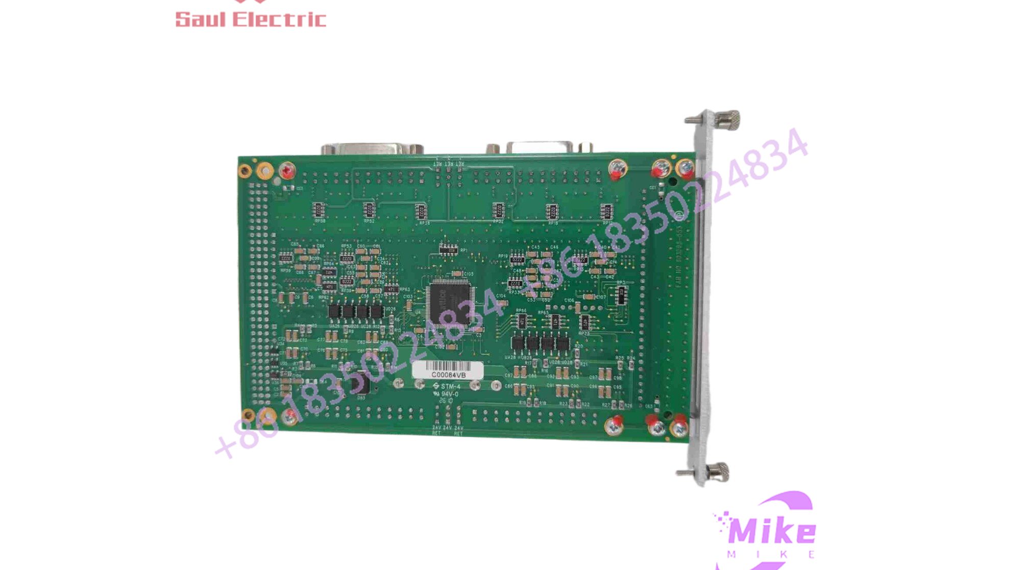
ACC-68E
Key Technical Specifications
| Parameter | Specification Detail |
| Primary Architecture | Dedicated pulse-and-direction (PFM) output processor core |
| System Compatibility | UMAC Turbo, Turbo PMAC, and compatible motion controller racks |
| Control Outputs | Differential pulse and direction line driver outputs per axis |
| Feedback / Auxiliary I/O | Home flags, over-travel limits, and amplifier/drive fault inputs |
| Maximum Pulse Frequency | High-speed output capability configured for microstepping drives |
| Field Termination | Standard industrial terminal blocks / D-SUB interfaces |
| Form Factor & Mounting | 3U industrial rack-mount module (plugs into backplane expansion port) |
Global Sourcing & Live-Test SOP
Sourcing surplus pulse-train interface cards requires strict electronic validation to ensure line drivers and output buffers maintain clean square-wave edges without ringing or signal degradation:
- Inbound Verification: Board part numbers, layout revisions, and backplane connector pins are audited against authentic Delta Tau build documentation.
- Live Rack Simulation: The card is mounted onto a verified UMAC test backplane, confirming proper communication registration and address mapping across the internal bus.
- Diagnostics: Using an oscilloscope and a multi-axis pulse counter, we stream maximum-frequency pulse and direction patterns through the output channels. We verify edge-rate integrity, signal amplitude stability, and proper latching on all auxiliary limit inputs.
- Final Prep: Approved units are cleaned, fitted with protective connector covers, and sealed in heavy-duty anti-static moisture-barrier bags.
The Field Engineer’s Pitfall Guide
❗ Pulse Timing and Width Mismatches: Stepper drives require specific minimum pulse-on and pulse-off times to correctly register step commands. If your PMAC software configuration sets pulse widths narrower than what your specific physical drive can handle, the motor will stall or drop steps at high speeds.
❗ Unshielded Stepper Cabling: Running long, unshielded pulse-and-direction control lines parallel to high-current motor power cables will induce electrical noise, causing the stepper drive to misinterpret noise spikes as extra steps and ruining position accuracy.
❗ Base Address Jumper Conflicts: The ACC-68E relies on physical switch or jumper settings to define its base memory address on the expansion backplane. Installing a replacement board without matching the original address offsets will cause communication blindness with the PMAC CPU.
Intent-Driven FAQ
Can the ACC-68E process encoder feedback from the stepper motor?
While the ACC-68E is engineered primarily to output step-and-direction command trains, complete closed-loop stepper configurations typically coordinate feedback signals through companion encoder interface cards within the same UMAC rack.
How many axes does a single ACC-68E card support?
The is configured as a multi-axis pulse-train interface board, providing dedicated step and direction channels tailored for standard multi-axis stepper applications.
Do I need to modify my PMAC motion program when replacing this board?
If you are replacing an exact, failed hardware match with identical base address switch settings, your existing axis definition and pulse-scaling parameters will execute immediately upon boot.
What causes a stepper motor to jitter or vibrate without rotating?
This typically points to incorrect phase wiring, an open direction line (causing the motor to rapidly reverse back and forth between steps), or incorrect current settings on the external stepper drive.
What warranty is included with surplus units?
Every unit shipped from our stock is backed by a comprehensive 12-month operational warranty covering driver output health, pulse-train timing stability, and power regulation circuits.





