


Description
Control Techniques DCD60X7/14 | Mini Maestro DC Servo Drive
Key Technical Specifications
- Drive Family: Mini Maestro
- Motor Type: Brushed DC servo motor
- Nominal Supply: 60 VDC
- DC Supply Range: 24–72 VDC
- Rectified AC Supply Range: 20–80 VDC, with maximum 2 V peak-to-peak ripple
- Nominal Output Current: Adjustable from 2 to 7 A
- Peak Output Current: 14 A for 2 seconds
- Peak Current Adjustment: 50–100% through the RIP resistor on SK1
- Nominal Current Adjustment: Through the RIN resistor on SK1
- Feedback Options: Tachogenerator or armature-voltage feedback
- Protection: Heatsink overtemperature, undervoltage, and overvoltage protection
- Control Reference: Analog speed and current references; ±10 V reference inputs are documented
These ratings are drawn from the Mini Maestro User Guide. The specific unit’s hardware revision and adjustment components should be verified before installation.
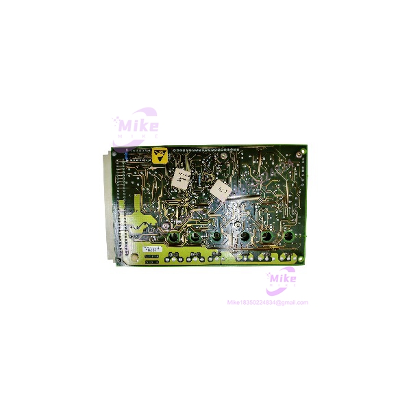
DCD60X7/14
Global Sourcing & Live-Test SOP (Transparency Core)
A surplus DCD60X7/14 should not be accepted as operational merely because its heatsink is clean and its terminals look undamaged. This is a power-electronics assembly; prior overloads, thermal cycling, and poor storage can leave faults that a visual inspection will never catch.
The following is a recommended buyer-side qualification SOP. It is not a representation that the specific eBay-listed unit has passed these tests.
Inbound Verification
Before the drive enters stock:
- Match the DCD60X7/14 model marking against the nameplate and PCB identification.
- Record serial number, hardware revision, and available OEM traceability documentation.
- Inspect power terminals, edge connector, PCB, heatsink, and mounting surfaces for corrosion, cracks, contamination, or evidence of rework.
- Examine solder joints and accessible power components for heat damage.
- Compare the unit with the applicable Mini Maestro documentation and the buyer’s existing drive.
A seller’s “new surplus” description is a condition claim, not proof of factory origin or electrical performance. Request clear photographs of the actual unit, not catalog images.
Live Simulation & Functional Testing
Use a properly protected DC motor-drive test bench with a compatible brushed DC motor or an engineered load arrangement. Do not energize an unknown unit directly from the production machine.
The recommended test sequence:
- Verify the supply arrangement and polarity against the applicable Mini Maestro manual.
- Inspect the installation kit and edge connector before applying power.
- Confirm the RIN and RIP current-adjustment settings.
- Apply a current-limited supply within the documented operating range.
- Verify enable behavior and analog reference response.
- Check motor direction, speed response, and current-monitor output under controlled conditions.
- Confirm that the drive does not trip unexpectedly during a controlled load transition.
Important: The Mini Maestro supply terminals are not isolated from the control terminals. The manual warns that the supply must either be isolated or have its negative pole grounded. The heatsink can also be live. Use an appropriately engineered test setup and follow the OEM safety instructions.
Diagnostics & Burn-In
A meaningful acceptance report should include:
- DC supply voltage at the drive
- No-load and loaded motor-current readings
- Speed-reference versus motor-response observations
- Current-monitor output
- Thermal observations during operation
- Protection behavior, tested only under controlled conditions
A 24-hour heat run may be specified for critical spares, but it is not a substitute for load testing and should not be claimed unless actually completed.
The DCD60X7/14 is an analog DC drive, not a networked PLC communication module. Modbus RTU or Profibus handshake testing is therefore not an appropriate default acceptance test for this model.
Final Preparation & Shipment
Before dispatch, document the exact model, hardware revision, inventory condition, and completed test results. Record the current-adjustment settings where they can be verified, and protect the unit with ESD-safe packaging and mechanical support around the terminals.
For a production-critical replacement, request the actual test report and written warranty terms before issuing the purchase order.
The Field Engineer’s Pitfall Guide
❗ Warning 1: Do Not Assume the RIN and RIP Settings Match Your Existing Drive
The Mini Maestro uses the RIN resistor on SK1 to adjust nominal current and the RIP resistor to adjust peak current. A replacement drive with different settings can change the motor’s current limit and overload behavior, even when the model number matches.
I’ve seen replacement work become a second commissioning job because the incoming drive was treated as a drop-in unit without checking its adjustment components. Record the existing settings before removal and verify them against the motor’s rated current and the machine’s approved configuration.
❗ Warning 2: The DC Supply and Control Terminals Are Not Isolated
The Mini Maestro manual explicitly warns that its supply terminals are not isolated from its control terminals. The heatsink can also be live. Never assume that low-voltage DC means the drive is safe to handle while energized.
Before replacement, isolate the supply, verify the absence of hazardous voltage with appropriately rated test equipment, and follow the OEM discharge and handling procedure. The manual specifies a minimum 10-second wait after switching off the supply, but that interval should not replace voltage verification.
❗ Warning 3: Feedback Type and Motor Inductance Matter
The Mini Maestro supports tachogenerator and armature-voltage feedback arrangements. A replacement configured for the wrong feedback method can produce poor speed regulation or unstable motor behavior.
Also check motor inductance. The manual calls for a choke when motor inductance is below 1 mH, among other specified conditions. If the original installation includes an L11 choke, do not remove it simply because the replacement drive appears physically identical.
Intent-Driven FAQ
Q1: Will the DCD60X7/14 run my existing DC servo motor?
Potentially, provided the motor’s voltage, continuous current, peak current, feedback method, and inductance are compatible with the drive and its configured limits. The 7 A nominal and 14 A peak ratings are drive limits—not confirmation that every motor within those figures is suitable.
Q2: Can I replace the DCD60X7/14 with another Mini Maestro model?
Not automatically. Other Mini Maestro models have different current ranges and peak ratings. A higher-current variant is not necessarily a safe substitute for the original motor and machine configuration. Verify the full model designation, mounting arrangement, supply requirements, and current settings before approving a substitution.
Q3: Is the Control Techniques /14 obsolete?
The model is listed as discontinued by some industrial spare-parts suppliers. Repair and replacement services are still advertised, but current OEM production status and factory-new availability should be confirmed directly.
Q4: Can I hot-swap the /14?
Do not assume so. Although the Mini Maestro design allows front access for removal from its rack arrangement, that does not establish permission for energized replacement. Isolate the supply and follow the applicable machine and drive maintenance procedures before removing the unit.
Q5: Can the /14 be used with a PLC?
Yes, as part of a properly engineered control arrangement. Its analog speed and current-reference interfaces can be connected to compatible PLC analog outputs, provided the signal ranges, common references, enable circuit, and grounding arrangement are correctly engineered. It is not a direct fieldbus drive with native Modbus RTU or Profibus connectivity established by the cited Mini Maestro documentation.
Q6: What should I check before buying a used /14?
Request actual-unit photographs, model and revision confirmation, condition disclosure, and documented functional test results. For critical applications, ask whether the supplier tested the drive under load and verified its current-reference response. Confirm the warranty and return terms in writing.
Q7: Does the replacement come with a warranty?
Warranty coverage depends on the seller and the inventory condition. Some industrial repair suppliers advertise 12-month coverage for their repair and replacement services, while other suppliers offer different terms. Do not assume that a third-party warranty is an OEM warranty. Obtain written confirmation of duration, exclusions, return procedure, and whether the warranty covers the complete drive or only repaired components.





