

Description
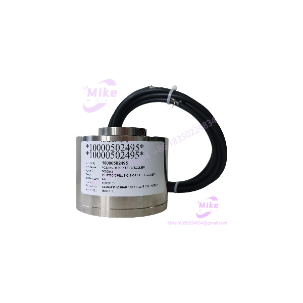
BEI Sensors GEUX30-1000-001 | 1000 PPR Incremental Encoder
Product Introduction
The BEI Sensors GEUX30-1000-001 is built for applications where encoder feedback has to survive more than a clean laboratory environment. It is an optical incremental encoder from the GEUX30 family, configured with a hollow shaft, 30 mm shaft interface, 1,000 pulses per revolution, push-pull A/B/Z output, and an 11–30 VDC supply range. The documented configuration also carries ATEX hazardous-area certification.
That combination makes the GEUX30-1000-001 more application-specific than a generic 1,000-PPR encoder. The shaft arrangement, output electronics, cable construction, supply range, phasing, and hazardous-area approval all need to agree with the existing machine. A replacement encoder that merely matches the pulse count can still produce incorrect direction feedback, incompatible electrical levels, or a mechanically unusable installation.
The model is also listed by current component distributors as a BEI Sensors encoder under the Sensata product family, confirming the exact manufacturer part number rather than treating GEUX30-1000-001 as a generic GEUX30-series designation.
GEUX30-1000-001
Key Technical Specifications
- Manufacturer: BEI Sensors
- Part Number: GEUX30-1000-001
- Encoder Type: Optical incremental rotary encoder
- Series: GEUX30
- Resolution: 1,000 PPR
- Mechanical Configuration: Hollow shaft
- Shaft Diameter: 30 mm
- Supply Voltage: 11–30 VDC
- Output: Push-pull
- Signal Channels: A / B / 0
- Quadrature Sequence: B before A
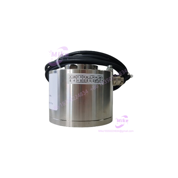
- Cable: PUR, side exit
- Cable Length: 3 m
- Hazardous-Area Certification: ATEX 2014/34/EU
- Hazardous-Area Classification: Ex II 2 GD
- Gas Protection: Ex d IIC
- Temperature Classes: T6 / T5 / T4
- Equipment Protection Level: Gb
- Country of Origin Listed by Distributor: France
The -1000-001 configuration record specifically identifies the 1,000 PPR resolution, 11–30 VDC supply, push-pull A/B/0 output, 30 mm shaft, 3 m PUR cable, and ATEX Ex d IIC classification.
What the 1,000 PPR Rating Means
At 1,000 pulses per revolution, the encoder provides 1,000 output cycles per revolution on the specified pulse channel. In a quadrature system, the controller can use the relationship between A and B to determine direction as well as rotational movement.
Do not automatically convert the manufacturer’s PPR figure into a controller’s counts-per-revolution value. A drive or motion controller may count rising edges, both edges, or use quadrature x4 processing. The resulting count can therefore differ from the encoder’s stated PPR.
For commissioning, use the controller manufacturer’s counting convention rather than assuming 1,000 PPR = 1,000 counts.
Global Sourcing & Live-Test SOP
1. Inbound Verification
For a hazardous-area encoder, identification should begin with the nameplate and certification markings.
Record:
- Complete part number
- Manufacturer marking
- Serial number
- Certification markings
- ATEX information
- Shaft diameter
- Cable length
- Connector or termination arrangement
- Physical condition
- Any additional suffixes or factory configuration codes
Photograph the nameplate and certification markings before installation.
Do not substitute another model merely because its body appears identical. The family contains multiple resolutions and configurations, including 256, 512, 720, 1,024, 2,048, and higher-count variants.
2. Mechanical Inspection
Inspect the hollow shaft carefully.
Check:
- Shaft bore condition
- Shaft clamping area
- Keyway or anti-rotation arrangement if applicable
- Bearing condition
- Housing damage
- Mounting hardware
- Cable gland/exit
- Cable jacket
- Connector or termination
Do not force the encoder onto the motor shaft. A 30 mm hollow shaft is a specific mechanical interface, and an apparently minor shaft mismatch can damage the encoder bearing or create excessive radial loading.
3. Electrical Test
Before connecting the encoder to a PLC, motion controller, or drive:
- Verify the controller’s input voltage compatibility.
- Confirm the encoder supply polarity.
- Verify the actual A/B/Z wiring against the unit’s documentation.
- Apply a controlled 11–30 VDC supply.
- Confirm the current draw is consistent with the applicable documentation.
- Rotate the shaft manually at low speed.
- Monitor A and B simultaneously.
- Confirm the expected quadrature relationship.
- Verify the index/zero pulse once per revolution where applicable.
A Fluke multimeter is useful for supply-voltage verification, but an oscilloscope or encoder diagnostic instrument is preferable for checking A/B phase relationship and signal integrity.
4. Quadrature Verification
The specified configuration uses B-before-A phasing.
That detail should be checked during commissioning rather than assumed.
If the controller reports reverse motion:
- Do not immediately declare the encoder defective.
- Verify A/B channel assignment.
- Confirm the controller’s direction convention.
- Check whether the machine’s mechanical rotation direction is opposite to the expected reference.
- Confirm that the actual encoder configuration matches the ordered suffix.
Swapping A and B can change perceived direction, but that should be treated as a controlled wiring/configuration decision, not a substitute for verifying the correct encoder model.
5. Extended Test
For a production spare, test the encoder over a representative speed range.
Monitor:
- A/B waveform quality
- Index pulse
- Direction detection
- Missed counts
- Cable movement
- Bearing noise
- Housing temperature
- Signal stability after warm-up
Where the encoder is intended for hazardous-area service, the functional test does not replace the applicable installation, inspection, and certification requirements for the actual hazardous location.
6. Final QC Documentation
Record:
- t model:
- Resolution: 1,000 PPR
- Supply range
- Output type
- A/B/Z configuration
- Phasing
- Shaft diameter
- Cable length
- Certification markings
- Test equipment
- Test speed/range
- Test result
- Physical condition
Package the encoder to prevent impact to the shaft and protect the cable from sharp bends during international shipment.
Field Engineer’s Pitfall Guide
❗ Warning 1 — Do Not Match Only the 1,000 PPR Rating
A 1,000-PPR encoder is not automatically a replacement for the .
The combines a specific hollow-shaft mechanical configuration with 11–30 VDC supply, push-pull output, A/B/Z signals, B-before-A phasing, and hazardous-area certification.
Every one of those characteristics can affect replacement compatibility.
❗ Warning 2 — Verify the Hazardous-Area Certification
ted configuration is associated with ATEX 2014/34/EU, Ex II 2 GD, Ex d IIC, with T6/T5/T4 temperature classifications.
Do not assume that another encoder with the same PPR and shaft size carries the same certification. In a hazardous installation, the certification marking is part of the equipment specification.
❗ Warning 3 — Confirm the 30 mm Hollow-Shaft Interface
The 30 mm hollow shaft is a mechanical specification, not just a descriptive feature.
Before installation, verify the motor or machine shaft diameter, available insertion depth, clamping arrangement, concentricity, and anti-rotation method. Excessive shaft misalignment can damage bearings and create encoder runout or intermittent feedback faults.
Intent-Driven FAQ
Whaors ?
The is an optical incremental rotary encoder in the family. The documented configuration is rated at 1,000 PPR and uses a 30 mm hollow shaft with push-pull A/B/0 outputs.
What of ?
The specified resolution is 1,000 PPR. The controller’s final counts-per-revolution value can differ depending on whether it uses single-edge, dual-edge, or quadrature x4 counting.
Wthe require?
The documented configuration specifies an 11–30 VDC supply range.
What output does this encoder use?
The configuration is specified with push-pull A/B/0 outputs and B-before-A quadrature phasing.
Is the suitable for hazardous areas?
The documented configuration carries ATEX hazardous-area certification, including Ex II 2 GD and Ex d IIC classifications with T6/T5/T4 temperature classes. The actual installation must still comply with the applicable hazardous-area requirements and the encoder’s certification documentation.
What is the shaft size?
fied uses a 30 mm hollow shaft.
How long is the supplied cable?
The identified configuration uses a 3 m PUR side cable.
Can I replace it with another encoder?
Not solely on the basis of the family name. The family contains multiple resolutions and configurations. Verify PPR, supply voltage, output electronics, shaft configuration, cable arrangement, phasing, and hazardous-area certification before substitution.





