

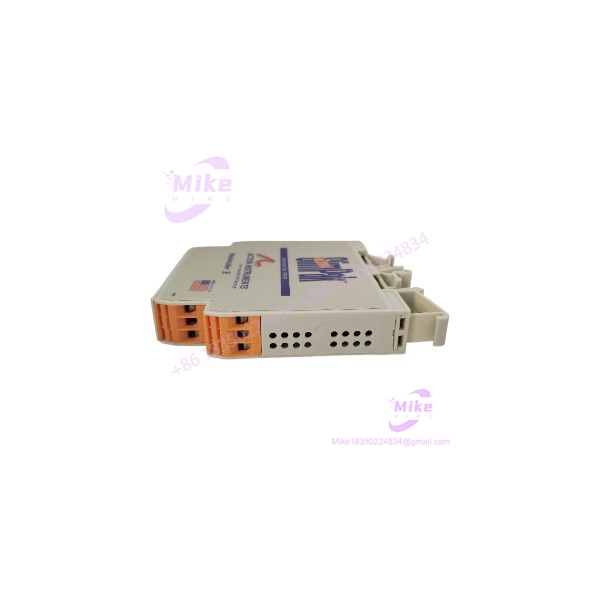
Description
Action Instruments G448-0002 | Bridge Signal Conditioner
Dynamic Product Introduction
A bridge or strain-gauge signal is not something you want to route through a generic analog converter and hope the scaling works. The G448-0002 is designed specifically for that low-level measurement problem, combining excitation, signal conditioning, configurable scaling, and galvanic isolation in a compact DIN-rail package.
The important engineering advantage is configuration range rather than raw processing speed. The G448-0002 accepts input signals from 10mV through ±200mV, corresponding to approximately 0.5mV/V to greater than 50mV/V for bridge applications. Its adjustable excitation can be set from 1 to 10V with up to 120mA drive, while the output can be configured for either voltage or current transmission. That makes the G448-0002 practical for weighing systems, pressure measurement, force measurement, and other bridge-based instrumentation where millivolt-level signals are vulnerable to ground-loop and noise problems.
For legacy installations, the three-way isolation is particularly relevant. The G448-0002 isolates input, output, and power, with a specified 1800VDC isolation rating. That is a meaningful distinction when replacing an older conditioner that has become difficult to source (especially where the existing control cabinet has accumulated multiple analog ground references).
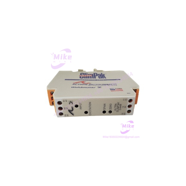
G448-0002
Key Technical Specifications
- Model: G448-0002
- Series: Ultra SlimPak G Series
- Application: Bridge and strain-gauge signal conditioning
- Mounting: DIN rail
- Input range: 10mV to ±200mV
- Bridge sensitivity range: Approximately 0.5mV/V to >50mV/V
- Input impedance: >1MΩ
- Excitation: 1–10V adjustable
- Excitation drive: Up to 120mA
- Analog voltage outputs: 0–5V and 0–10V
- Analog current outputs: 0–1mA, 0–20mA, and 4–20mA
- Voltage-output drive: Up to 10mA
- Current-output compliance: Up to 12V for 0–20mA and 4–20mA configurations
- Isolation: 1800VDC maximum between input, output, and power
- Power supply: 9–30VDC in current documentation; some older documentation specifies 18–30VDC, so the actual nameplate/datasheet revision should be checked before installation.
- Configuration: DIP-switch selectable input/output functions with zero and span adjustment
- Input adjustment: Up to 50% zero and span adjustment within the selected input range
- Diagnostic indication: Front LED indicates power/input status and provides different flash rates for out-of-range conditions.
Global Sourcing & Live-Test SOP
For surplus inventory, the correct approach is to treat the device as an instrumentation component rather than simply checking whether the LED illuminates.
1. Inbound Verification
First, verify the physical identification against and inspect the housing, terminal markings, configuration switches, adjustment controls, and manufacturing labels.
Serial-number and label information should be photographed and recorded before the unit enters inventory. Packaging condition, visible oxidation, terminal damage, cracked plastic, and evidence of previous cabinet installation should also be documented.
For international procurement, retain the available commercial and manufacturer documentation with the inventory record. Do not assume that an identical-looking Ultra SlimPak module has identical configuration settings.
2. Live Simulation
A proper bench procedure should use a regulated DC supply and calibrated instrumentation rather than applying power and declaring the unit functional.
For a evaluation, the test rack should provide:
- Regulated 24VDC supply
- Calibrated millivolt signal source
- Appropriate bridge/strain-gauge simulation
- Precision multimeter
- Current-loop measurement capability
- Suitable resistive load for voltage/current output verification
The input should be driven through representative points across the configured range. The output should then be measured against the expected transfer function.
A Fluke-class calibrated multimeter is appropriate for this verification, although the exact instrument should be selected according to the required accuracy.
3. Diagnostic Validation
The uses configurable input ranges and output modes rather than software-based protocol configuration. Consequently, the critical validation is analog signal integrity—not a Modbus or Profibus handshake.
Check:
- Power-up behavior
- LED indication
- Input zero
- Input span
- Output zero
- Output span
- Direct/reverse operation where configured
- Excitation voltage
- Output loading
- Isolation between input, output, and power
The published documentation identifies 11 switch-selectable input ranges and adjustable zero/span controls. Calibration should therefore be performed only after confirming the DIP-switch configuration.
For an incoming surplus unit, a 24-hour powered heat run is a useful additional screening step when the application is production-critical. Record supply voltage, ambient conditions, output drift, and any abnormal LED behavior throughout the test.
4. Final Preparation
Record the exact configuration before shipment, including:
- Input range
- Excitation setting
- Output type
- Output range
- Direct/reverse setting
- Zero adjustment
- Span adjustment
The unit should then be protected in ESD-conscious packaging with terminal protection where appropriate.
One important distinction: this is a configurable analog signal conditioner, not a programmable PLC CPU. There is no user logic program to back up or firmware image to preserve in the same sense as an ABB, Siemens, or Allen-Bradley controller.
The Field Engineer’s Pitfall Guide
❗ Do not change the DIP switches with power applied.
The manufacturer documentation explicitly warns against changing switch settings while energized because severe damage can result. Remove DC power, verify the circuit is de-energized, configure the switches, then restore power.
❗ Do not assume the replacement has the same configuration as the failed unit.
The is field configurable. A replacement may be set for a completely different input/output combination. I’ve seen this type of mistake turn a five-minute replacement into hours of troubleshooting because a technician copied the wiring but not the internal switch configuration. Photograph the original settings before removal whenever possible.
❗ Verify excitation and output loading before connecting the plant circuit.
A bridge transmitter may look electrically correct while the excitation voltage or output mode is wrong. The can provide 1–10V excitation with up to 120mA drive, while its voltage and current outputs have different loading requirements. Verify the actual transmitter wiring and receiving-device impedance before energizing the loop.
Intent-Driven FAQ
Will I lose my logic program if I replace the ?
No. The is an analog signal conditioner, not a programmable controller CPU. There is no PLC logic program stored in the module. The critical replacement data is the electrical configuration: input range, excitation, output type, output range, and calibration.
Can the replace an older bridge signal conditioner?
Potentially, but electrical compatibility must be checked rather than assumed. Confirm the bridge excitation requirement, millivolt signal range, required output, power supply, terminal arrangement, and isolation requirements. The supports a broad range of bridge applications, but that does not make every older conditioner a direct wiring replacement.
Is the obsolete?
The model has a long field history, and some current industrial inventory sources identify versions such as as discontinued. That makes configuration verification and condition testing particularly important when sourcing replacement or surplus inventory.
Can I hot-swap the ?
Do not treat it as a hot-swappable I/O module. The documentation specifically warns against changing configuration switches under power. For a production replacement, isolate the DC supply and associated instrumentation circuit according to the plant’s electrical safety procedure before removing or configuring the unit.
Can the firmware be downgraded if the replacement does not behave like the old unit?
Firmware management is generally not the relevant issue with the . Unlike a PLC or DCS processor, its operation is based on hardware configuration, analog circuitry, DIP-switch settings, and calibration. If behavior differs after replacement, inspect those parameters before looking for a firmware problem.
What should I verify before ordering a ?
At minimum, verify the exact model, required input millivolt range, bridge sensitivity, excitation voltage/current, output type, output range, supply voltage, terminal arrangement, and physical condition. For surplus inventory, request photographs of the actual unit and configuration markings when those details affect your application.
What warranty should I expect with a surplus ?
Warranty coverage depends on the individual seller and the specific inventory condition. Do not interpret the manufacturer’s historical documentation as a current seller warranty. Before purchase, confirm in writing whether the unit is factory sealed, unused, refurbished, or previously installed, and determine exactly what is covered in the event of functional failure.





