Description
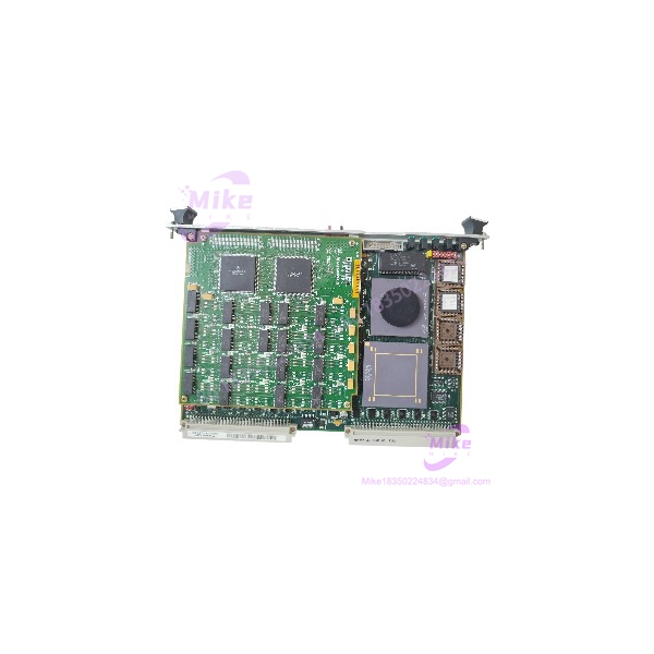
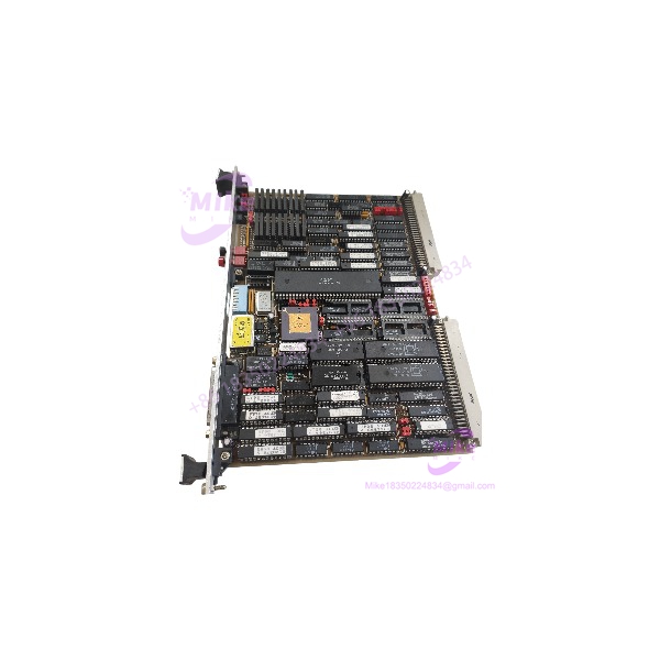
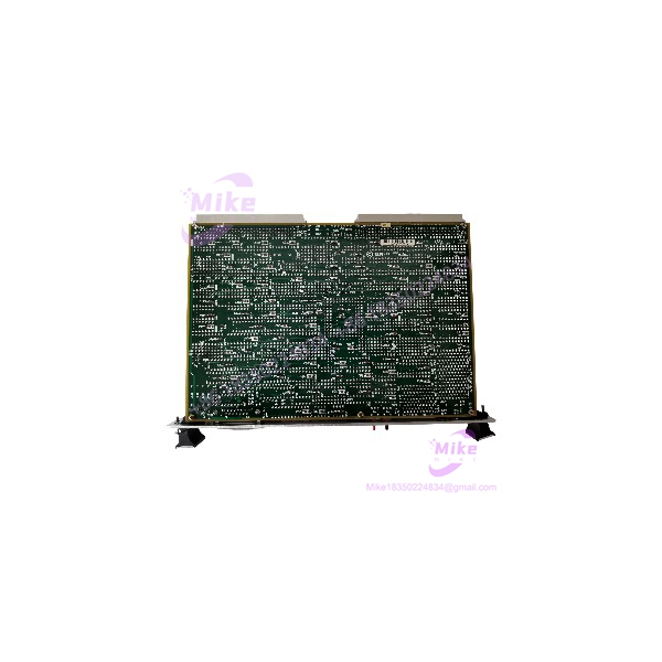
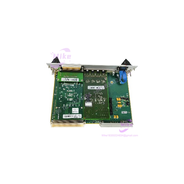
Motorola PMCspan | 6U VMEbus PMC Mezzanine Carrier Board
Product Introduction
When an aging VMEbus control computer runs out of slot real estate for new communication or data acquisition cards, a complete system redesign is rarely financially viable. The Motorola PMCspan isn’t a standard backplane slot extender; it is a specialized mezzanine carrier board engineered specifically to mount directly onto compatible Motorola and Emerson single-board computers—such as the MVME2300, MVME2400, MVME5100, and MVME5500 series. Trying to fit modern I/O into legacy 6U VME chassis without a dedicated carrier solution leads to massive mechanical and electrical incompatibilities—making this expansion module essential for system upgrades.
Operating inside rugged defense, aerospace, and heavy industrial enclosures requires hardware that withstands thermal and mechanical stress. The PMCspan uses an onboard transparent PCI-to-PCI bridge to map mezzanine cards straight to the host CPU’s local bus with near-zero latency. Built-in stacking connectors allow you to cascade multiple carriers—though you must carefully evaluate total chassis slot spacing and 5V/3.3V power budget limits on the VME backplane before loading up multiple mezzanine boards.
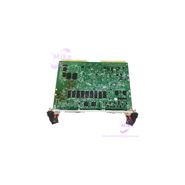
PMCSPAN
Key Technical Specifications
- Board Architecture: 6U VMEbus mezzanine expansion carrier board
- Host Compatibility: Designed for Motorola / Emerson VME single-board computers with local PCI expansion headers
- Mezzanine Capacity: Two (2) single-wide PMC modules or one (1) double-wide PMC module
- Bus Architecture: Transparent PCI-to-PCI bridge interface (utilizing industry-standard bridge silicon)
- Stackable Design: Cascadable architecture supporting multi-board stacking per single VME processor slot
- I/O Routing: Front-panel bezel access and optional rear-transition module (RTM) routing via P2 backplane
- Power Delivery: Draws 3.3V and 5V rail power directly from the host VME SBC and backplane bus
- Operating Temperature Range: 0°C to +55°C (32°F to 131°F) standard air-cooled (conduction-cooled variants available)
- Storage Temperature Envelope: -40°C to +85°C (-40°F to +185°F)
- Relative Humidity Tolerance: 5% to 95% non-condensing operating environment
- Mechanical Form Factor: Standard 6U VMEbus single-slot footprint (IEEE 1101 compliant with injector/ejector handles)
Application Scenarios & Pain Points
A naval radar telemetry station in Virginia needed to add high-speed fiber optic network PMC cards into their existing 6U VMEbus processing racks, but all available chassis slots were completely occupied. Installing the Motorola PMCspan onto their existing MVME5100 single-board computers allowed them to stack dual PMC cards directly on top of the host processor, doubling their I/O density without requiring a costly total chassis redesign.
With vs. Without Mezzanine Carrier Boards:
- Without the Motorola PMCspan: Upgrading legacy VME systems requires ripping out established backplanes and replacing entire processor racks, driving upgrade costs into the hundreds of thousands of dollars.
- With the Motorola PMCspan: Modular mezzanine carriers extend the life of existing VME single-board computers by enabling seamless integration of modern serial, MIL-STD-1553, or network cards.
Aerospace Ground Support & Flight Simulators:
- Condition: Continuous multi-shift testing operations running inside high-vibration equipment racks.
- Impact: Sub-standard mezzanine adapters suffer from loose PCI connectors, signal reflection, and thermal lockups.
- Solution: The rigid aluminum framework and secure mounting standoffs of the Motorola PMCspan maintain absolute bus stability under continuous shock loads.
QA & Live Testing SOP (Trust Signal)
Every Motorola PMCspan carrier board passing through our facility goes through an unyielding verification protocol. We begin with a microscopic inspection of the high-density PCI connectors, stacking headers, and surface-mount bridge components to verify there is zero physical stress, bent pins, or trace oxidation. Next, the PMCspan is mounted onto a verified host VME single-board computer test rig inside a powered 6U chassis—we measure bus voltage regulation across the 3.3V and 5V rails using a calibrated Fluke digital multimeter.
During live functional testing, we install representative PMC communication cards onto the carrier slots and run continuous data-throughput stress tests across the PCI-to-PCI bridge. We verify zero dropped packets, correct interrupt routing, and thermal stability during a 24-hour burn-in run. Once cleared, the board is wiped down, fitted with protective anti-static covers, and vacuum-sealed in heavy-duty ESD packaging with custom foam cushioning.
Field Engineer’s Pitfall Guide
❗ GOTCHA #1: VME Backplane Power Rail Overload Do not stack multiple PMCspan boards loaded with high-draw specialty PMCs without calculating your chassis power supply capacity. Drawing excessive 3.3V or 5V current through the host SBC expansion header will cause voltage droop, resulting in random CPU reboots and PCI bus parity errors.
❗ GOTCHA #2: Mezzanine Standoff Height Clearance When mounting double-wide or tall component-side PMCs onto the PMCspan, verify your standoff heights and component clearance. Using incorrect standoff spacers will cause the underside of the mezzanine card to short out against the carrier board traces, instantly frying onboard logic.
❗ GOTCHA #3: Host BIOS and Driver Device Tree Configuration When adding new PMC cards via a PMCspan to an older operating system build (such as VxWorks or legacy Linux kernels), ensure your board support package (BSP) device tree correctly maps secondary PCI bridge bus numbers. Unrecognized bridge hierarchies will cause the OS to fail at recognizing attached mezzanine devices.
Intent-Driven FAQ
What is the primary purpose of the Motorola PMCspan?
The Motorola PMCspan is a 6U VMEbus mezzanine carrier board designed to let VME single-board computers host PCI Mezzanine Cards (PMCs), effectively expanding system I/O capabilities without consuming extra VME chassis slots.
Can I stack more than one PMCspan onto a single VME processor board?
Yes. The architecture is modular and cascadable, allowing you to stack multiple PMCspan boards onto a single host VME single-board computer, subject to physical slot clearance and VME chassis power budget limitations.
How many PMC modules can fit on a single PMCspan board?
Each standard PMCspan board accommodates either two single-wide PMC modules or one double-wide PMC module.
Is the PMCspan compatible with non-Motorola VME single-board computers?
While primarily engineered for Motorola and Emerson VME SBCs (like the MVME2300, 2400, 5100, and 5500 series) that feature local PCI expansion headers, compatibility with other manufacturers depends entirely on matching physical header pinouts and local bus bridge support.
What causes a “PCI Bus Master Timeout” error after installing a PMCspan?
A bus timeout usually indicates that the PMCspan carrier board is improperly seated into the host SBC expansion header, bent pins are shorting out bus lines, or the host processor’s PCI bridge registers are misconfigured in firmware.