Description
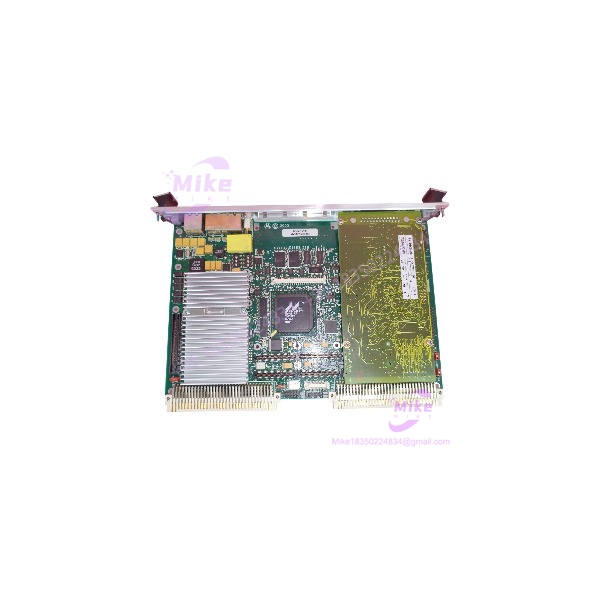
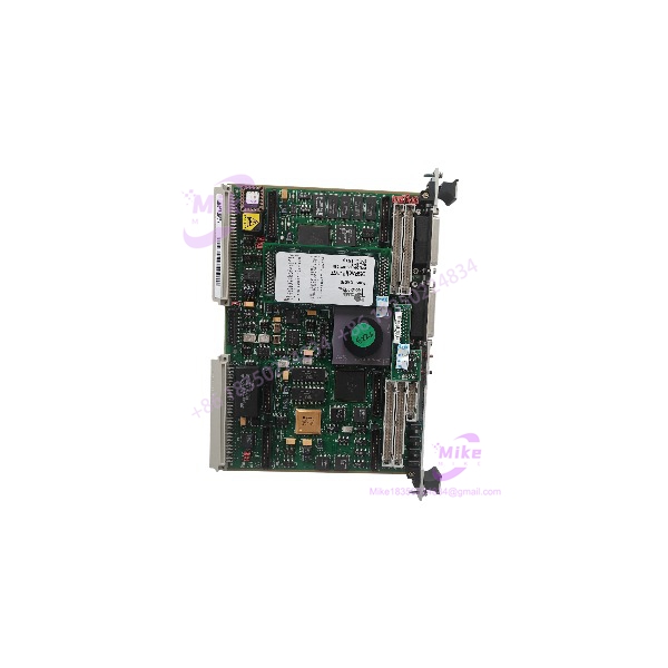
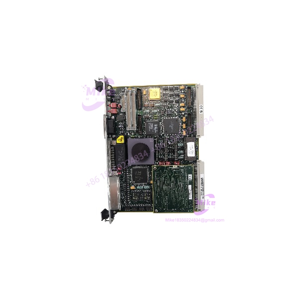
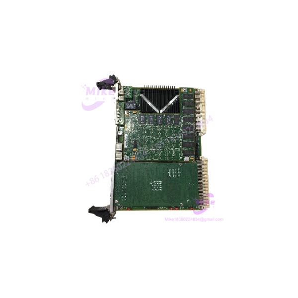
Motorola MVME2700-761 | VMEbus PowerPC Single Board Computer
Dynamic Product Introduction
Faced with sudden communication drops across rear connectors or unresolvable bus faults in an aging industrial control rack? When vintage processing nodes combined with dedicated rear transition boards experience thermal breakdown after decades of continuous operation, locating a fully integrated replacement ensures your plant avoids protracted downtime. The MVME2700-761 hardware bundle provides a dependable PowerPC processing engine paired with its corresponding rear transition module, maintaining precise pinout compatibility and signal integrity for legacy automation environments. Driven by a high-efficiency Motorola PowerPC MPC750 core with integrated L2 cache, this assembly delivers the deterministic performance required by demanding real-time control architectures.
Deploying a bench-tested, verified MVME2700-761 bypasses the component drift and hidden solder fatigue common in unmanaged surplus inventories. It restores native execution speeds, memory mappings, and rear I/O signal routing instantly, keeping critical industrial processes online without requiring an expensive, full-scale system rewrite.
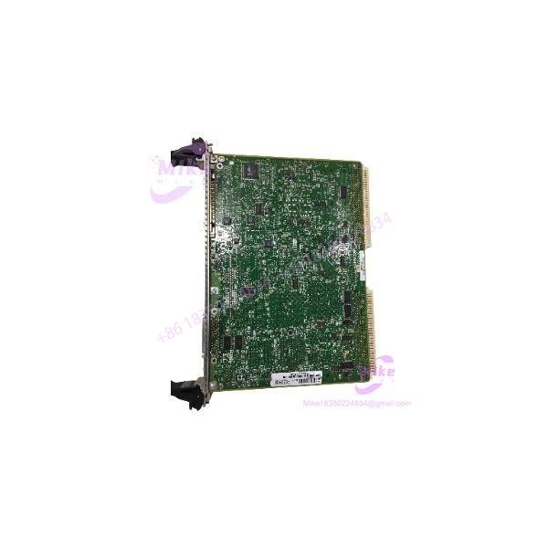
MVME2700-761
Key Technical Specifications
- Processor Architecture: Motorola PowerPC MPC750 RISC microprocessor
- Cache: L1 instruction/data cache and backside L2 cache
- On-Board Memory: High-density SDRAM with Error Correction Code (ECC) protection
- Flash Memory: Onboard flash storage for boot firmware and operating system images
- Bus Architecture: VMEbus IEEE 1014-1987 / ANSI/VITA 1-1994 compliant (Master/Slave interface)
- Rear I/O Transition: MVME761 transition module supporting rear-access serial, parallel, ethernet, and SCSI lines
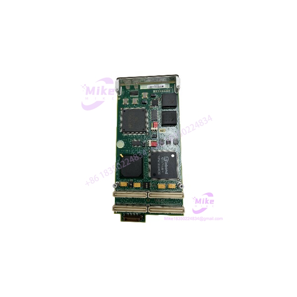
- Expansion Slots: Dual PMC (PCI Mezzanine Card) sites for modular I/O expansion
- Form Factor: Standard 6U VMEbus form factor (Double-Eurocard layout) with matching rear transition module
- Power Requirements: +5V and +3.3V DC primary backplane power rails
- Operating Temperature Range: 0°C to +55°C (32°F to 131°F) with mandatory chassis airflow
Global Sourcing & Live-Test SOP (Transparency Core)
Acquiring vintage hardware like the MVME2700-761 demands strict validation protocols to guarantee field reliability on active plant floors.
Inbound Verification
Incoming CPU boards and rear MVME761 transition modules undergo optical magnification checks to inspect PCB traces, connector pin alignment, solder joint integrity, and component date codes against original manufacturing specifications. Serial numbers are tracked to verify authentic OEM lineage and prevent counterfeit distribution.
Live Simulation
Every bundle is mounted in an active, temperature-controlled 6U VMEbus test chassis equipped with calibrated system controller cards, backplane load simulators, and rear test fixtures to replicate cabinet operating conditions.
Diagnostics
Testing executes comprehensive address and data pattern loops across the onboard ECC SDRAM space. We verify local PCI bus arbitration, test packet transmissions on network interfaces, check rear connector signal continuity on the transition module, and perform full-scale communication sweeps across serial ports. Units undergo a 24-hour thermal soak while tracking primary rail voltage stability using Fluke digital multimeters.
Final Prep
Upon clearing diagnostics, volatile registers are cleared, physical ejector handles and rear connector pins are inspected for mechanical tension, and the hardware is sealed inside heavy-duty anti-static shielding bags with desiccant protection.
The Field Engineer’s Pitfall Guide
❗ Rear Transition Module (MVME761) Pin Alignment: When installing the MVME2700-761, ensure the rear transition module is properly seated on the backplane P2 connector before sliding the CPU board home. Mismatched or forced rear pins can easily bend, causing intermittent signal drops or shorting auxiliary power lines.
❗ VME System Controller Configuration: Verify your jumper blocks for system controller assignment prior to installation. If a legacy slot configuration conflicts with the replacement board’s arbitration settings, the bus will lock up immediately upon power application.
❗ Memory Parity and ECC Mismatches: Verify that your real-time operating system kernel configuration matches the exact memory ceiling of the MVME2700-761. Bootloaders configured to look for extended memory blocks will generate fatal parity traps during initialization if memory size parameters are misaligned.
Intent-Driven FAQ
Will swapping out the MVME2700-761 erase my application software image?
The primary application software usually resides in non-volatile flash or external boot devices. However, you must verify your boot ROM settings and back up any battery-backed configuration registers before performing the hardware swap.
Can I hot-swap the MVME2700-761 in a live VMEbus chassis?
No. Standard VME architecture does not support live electrical hot-swapping for central processor cards. Always shut down system power completely and allow capacitors to discharge before inserting or removing the hardware.
What causes a continuous reset loop right after powering on the replacement board?
Continuous resetting is typically triggered by an unconfigured watchdog timer, low voltage sags on the backplane power rails, or an incorrect system controller jumper setting. Check your cabinet power supply output under load.
Are these replacement boards brand new or refurbished?
Since the original manufacturer has discontinued production, available units consist of fully reconditioned, factory-tested surplus inventory or verified working pulls backed by rigorous bench diagnostics.
What kind of warranty covers a surplus hardware purchase?
Reputable industrial automation suppliers provide comprehensive warranty coverage—typically one year—supported by complete documentation of individual board-level testing.