

Description
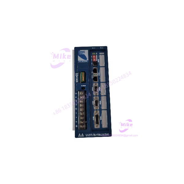
Danaher MMC-SD-0.5-230-D | Digital Servo Drive
Product Introduction
When a legacy motion axis refuses to come back online, replacing the drive with a visually similar unit is not enough. The MMC-SD-0.5-230-D is a digital-interface MMC Smart Drive designed to receive motion commands through the Digital Link architecture rather than the analog command input used by the analog-interfaced version. It belongs to the 230V single-phase MMC Smart Drive family and provides the motor power, feedback interface, I/O, and control electronics required for a closed-loop servo axis.
The electrical numbers are equally specific. At 230VAC, the MMC-SD-0.5-230-D provides 500W continuous output, with 1.8A RMS continuous current and 7.5A peak current. The drive accepts 100–240VAC nominal input, operates from 47–63Hz, and supports an output frequency up to 266Hz. Its digital control section includes a 125µs current-regulator update rate and 250µs velocity-regulator update rate — useful numbers when evaluating an old machine against its original motion-control requirements.
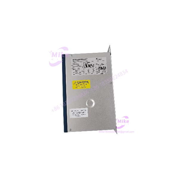
MMC-SD-0.5-230-D
Key Technical Specifications
- Model: MMC-SD-0.5-230-D
- Drive Family: MMC Smart Drive
- Interface Type: Digital-interfaced MMC Smart Drive
- AC Input: 100–240VAC nominal, single phase
- Absolute AC Input Range: 88–265VAC
- Input Frequency: 47–63Hz
- Nominal Input Current: 5A RMS
- Continuous Output Current: 1.8A RMS
- Maximum Continuous Current: 2.5A peak
- Peak Output Current: 7.5A
- Continuous Output Power at 230VAC: 500W
- Output Frequency: 0–266Hz
- 24VDC Logic Supply: 24VDC, +15% / −10%
- Typical 24VDC Consumption: 375mA / approximately 9W
- Current-Regulator Update Rate: 125µs
- Velocity-Regulator Update Rate: 250µs
- Operating Temperature: 7°C to 55°C / 45°F to 131°F
- Storage Temperature: −30°C to 70°C / −22°F to 158°F
- Humidity: 5–95% non-condensing
- Altitude: 1,500m / 5,000ft before specified derating
- Weight: Approximately 4.9lb / 2.23kg
- Digital Link Cable: Shielded, straight-pinned CAT5 or better
- Maximum Digital Link Cable Length: 30m / 98.4ft
- Encoder Feedback Frequency: Up to 720kHz
- Encoder Feedback Counting Rate: Up to 2.88 million counts/second
- General-Purpose Inputs: 8 optically isolated 24VDC inputs
- General-Purpose Outputs: 4 optically isolated 24VDC outputs
- Drive I/O Output Rating: 50mA maximum per output
- Compliance: CE marked; UL/CUL listed according to the manufacturer’s documentation
One important procurement detail: the manufacturer documents two configurations under the same MMC-SD-0.5-230-D model designation — one without BiSS and another with BiSS, associated with different internal part numbers. Do not assume a model-number-only match is sufficient when replacing a specialized feedback configuration.
Application Scenarios & Pain Points
Legacy Motion-Control Replacement
Without: A failed 500W servo axis forces an engineering team into a larger modernization project simply because the original drive is no longer sitting on the shelf.
With: A correctly matched MMC-SD-0.5-230-D can preserve the existing motion architecture, motor, feedback arrangement, and control strategy where the surrounding system remains compatible.
That matters on machines where rewriting motion logic creates more risk than replacing one failed drive.
High-Speed Feedback Applications
The feedback interface supports differential encoder signals with an input frequency up to 720kHz, corresponding to 2.88 million feedback counts per second. That gives engineers substantially more useful information than a vague “high-speed feedback” claim.
Hot Production Equipment
A packaging, converting, assembly, or material-handling machine may contain several identical low-power servo axes. One failed drive can stop an otherwise healthy mechanical section.
The 500W output class is particularly relevant when the original machine was engineered around smaller servo motors rather than a high-power axis. Replacing it with a substantially different drive class can introduce new tuning, wiring, protection, and motor-compatibility questions.
Legacy Digital Motion Networks
The Digital MMC Smart Drive receives commands through its Digital Link interface. The manufacturer specifies shielded CAT5-or-better cabling and a maximum cable length of 30m. This makes cable type and network topology part of the replacement assessment — not an afterthought.
Warm Control Cabinets
The specified operating range is 7°C to 55°C. Above 1,500m altitude, the manufacturer specifies a 3% derating for each additional 300m. A cabinet running at 50°C in a high-altitude plant therefore deserves more attention than a bench test at room temperature.
QA & Live Testing SOP
For a replacement servo drive, appearance is not a functional test.
Our preferred inspection sequence for an .5-230-D is:
- Identity verification: Confirm the complete model marking, configuration suffix, serial information, and physical nameplate before testing.
- Mechanical inspection: Check enclosure condition, terminal blocks, connectors, mounting points, cooling surfaces, and evidence of impact or corrosion.
- Electrical inspection: Verify that there is no obvious short between relevant power terminals and protective earth before energizing.
- Controlled power-up: Energize the drive on an appropriate test setup rather than installing an unverified unit directly into a production cabinet.
- 24V control check: Confirm the logic supply behavior against the documented 24VDC requirement.
- Digital interface check: Where the test system supports it, verify Digital Link communication and node/address configuration.
- Feedback test: Confirm the applicable encoder or feedback path rather than assuming every .5-230-D has the same feedback configuration.
- I/O verification: Exercise representative 24V inputs and outputs where the test fixture permits.
- Thermal observation: Monitor abnormal heating during sustained operation — a drive that passes a five-minute power-up but overheats under load has not passed a meaningful test.
- ESD-safe packaging: Protect connectors, control electronics, and exposed interfaces using appropriate ESD precautions during handling and shipment.
The manufacturer’s manual specifically documents power-on diagnostics, diagnostic LEDs, feedback connectors, Digital Link connections, and troubleshooting procedures, providing a useful framework for acceptance testing.
Field Engineer’s Pitfall Guide
❗ Do Not Treat Every .5-230-D as Identical
This is the big one.
Manufacturer documentation lists the .5-230-D in both a configuration without BiSS and a configuration with BiSS. Different internal part numbers are associated with those configurations. If the machine uses a specialized feedback arrangement, inspect the actual replacement unit before installing it.
❗ Digital Does Not Mean Analog-Compatible
The digital-interfaced MMC-SD receives motion commands through Digital Link. The analog-interfaced MMC-SD instead uses a 0 to +10V command input. Do not substitute one architecture for the other merely because the housing and base model appear similar.
❗ Check Cabinet Clearance and Grounding
The standard-width 500W drive is approximately 10.13in high × 3.69in wide × 6.12in deep. The manufacturer’s installation guidance also calls for appropriate mounting hardware and grounding. Measure the actual cabinet space before treating the replacement as a simple drop-in job.
And one more thing: do not hot-swap this drive on a live 230VAC system unless the complete machine architecture explicitly supports that procedure. The manufacturer’s safety documentation calls for qualified personnel and proper shutdown/service procedures.
Intent-Driven FAQ
Can I replace an older .5-230-D with another .5-230-D?
Generally, that is the correct starting point, but the model number alone should not close the investigation. Verify the feedback configuration, firmware/control configuration, Digital Link setup, motor compatibility, and physical revision before installation. The manufacturer lists multiple configuration variants under this model designation.
Is the .5-230-D a 230V servo drive?
Yes. It is part of the 230V single-phase MMC Smart Drive family. Its nominal input range is 100–240VAC, with an absolute specified range of 88–265VAC. At 230VAC, its continuous output power is 500W.
What is the peak current of the .5-230-D?
The specified peak output current is 7.5A. Continuous output current is 1.8A RMS, with the documentation also specifying 2.5A peak for the continuous-current rating.
Does the .5-230-D use Digital Link?
Yes. The D version belongs to the digital-interfaced MMC Smart Drive architecture and uses Digital Link connections. The documented maximum Digital Link cable length is 30m, with shielded CAT5 or better cable specified.
Can I use the analog 0–10V command input with the .5-230-D?
Do not assume so. The manufacturer’s documentation identifies the 0–10V command input specifically with the analog-interfaced MMC-SD, while the Digital MMC-SD receives motion commands through Digital Link.
What operating temperature does the .5-230-D support?
The documented operating range is 7°C to 55°C (45°F to 131°F), with storage specified from −30°C to 70°C. Humidity is specified at 5–95% non-condensing.
Is this a current-production or legacy drive?
The MMC Smart Drive documentation is legacy-era material, and the product family is associated with Danaher Motion/G&L Motion Control. For a surplus replacement, treat condition, exact configuration, and test evidence as separate purchasing criteria rather than relying solely on a catalog description. The manufacturer’s manual identifies the products as being manufactured and sold by G&L Motion Control, a Danaher Motion company.
What should I verify before ordering an .5-230-D?
Send the seller the complete nameplate information and existing drive configuration if possible. At minimum, verify the exact model, feedback type, Digital Link arrangement, motor model, input voltage, and required power rating. For legacy equipment, ten minutes spent checking the nameplate can prevent a much longer machine-down event.





