

Description
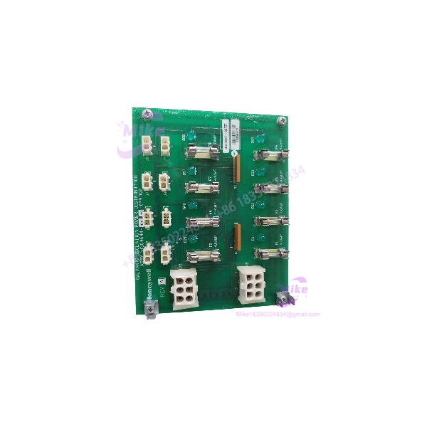
Honeywell MC-GPRD02 51304644-175 | GI Power Distribution
Product Introduction
The Honeywell MC-GPRD02 51304644-175 is a galvanic-isolation power distribution assembly used in Honeywell process-control I/O installations. Its job is straightforward but important: provide dedicated 24 VDC power distribution for galvanically isolated FTAs, which can require more field power than standard FTA arrangements.
This is therefore not an analog input/output card, pulse-input module, or controller. It belongs to the power-distribution layer of the Honeywell FTA architecture. Western Process Computers specifically identifies 51304644-175 as the “G/I Power Dist Assm CE CC”, while Honeywell planning material identifies MC-GPRD02 as the Power Distribution Assembly.
The -175 suffix matters during procurement. The available Honeywell hardware references distinguish the -150 and -175 versions, and the -175 configuration is associated with the CE/conformally coated implementation. A purchasing department should therefore retain the complete MC-GPRD02 / 51304644-175 designation rather than ordering only by the MC-GPRD02 family name.
MC-GPRD02 51304644-175
Key Technical Specifications
- Model: MC-GPRD02
- Part Number: 51304644-175
- Product Type: Galvanic Isolation Power Distribution Assembly
- Function: Dedicated 24 VDC distribution for galvanically isolated FTAs
- System: Honeywell DCS hardware
- Related Honeywell Variant: 51304644-150
- Configuration: GI power distribution
- Compliance: CE
- Construction: Conformally coated
- Mounting Architecture: FTA mounting-channel installation
- Input Supply: 24 VDC distribution architecture
- Output Function: Individual distribution of DC power to connected GI FTAs
- Typical Associated Hardware: Galvanically isolated analog, digital, and other FTA assemblies
- Part Number Alternate: 51304644175
Available supplier documentation states that the power-distribution assembly provides individually fused 24 VDC power for galvanically isolated FTAs.
A supplier specification gives up to 2 A per fused output and support for up to 16 FTA connections, but those figures should be treated as supplier-reported rather than OEM-confirmed until matched to the applicable Honeywell drawing for the installed system.
Global Sourcing & Live-Test SOP
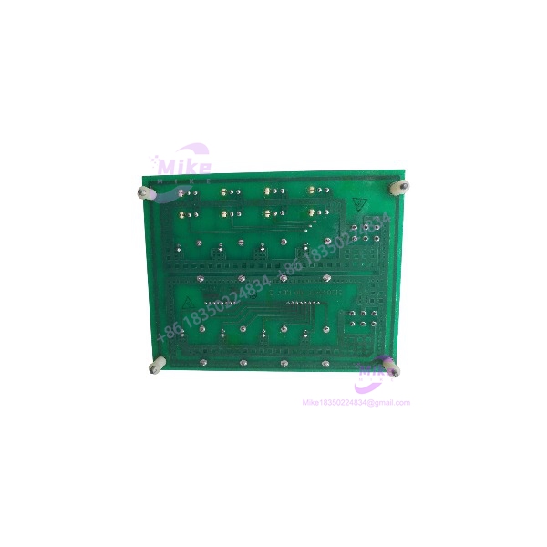
The MC- is a power-distribution assembly, so a proper receiving inspection should focus on the PCB, fusing, terminals, connectors, isolation-related circuitry, and physical condition rather than trying to evaluate it like an I/O signal card.
Recommended incoming inspection procedure:
- Part-number verification
Confirm the assembly is marked MC- / 51304644-175. - Revision and traceability capture
Record PCB revision, assembly revision, serial/manufacturing markings, and any additional Honeywell identification numbers. - Physical inspection
Examine the PCB, terminal blocks, connectors, fuse holders, mounting hardware, conformal coating, and soldered components for corrosion, cracking, contamination, or previous repair. - Coating inspection
Because the -175 version is associated with conformal coating, inspect the coating for lifting, cracking, contamination, or evidence of unauthorized rework. - Fuse and distribution-path verification
Verify fuse presence and ratings against the applicable Honeywell system documentation. Do not replace a fuse with a visually similar part having an unknown rating. - Controlled power test
If functional testing is part of the supplier’s service, apply the specified 24 VDC input using a current-limited test source and verify the appropriate distribution outputs. - Loaded test
Where practical, test representative outputs under an appropriate load rather than confirming only open-circuit voltage. - Isolation verification
Perform only the isolation checks specified by the applicable Honeywell documentation and qualified test procedure. - Documentation
Record input voltage, output measurements, fuse condition, channels/outputs tested, load conditions, and any functions not tested. - ESD-safe packaging
Protect the PCB and connectors against electrostatic discharge and mechanical impact during international shipment.
Test-status disclosure: These are recommended procurement and receiving procedures. They do not establish that a particular marketplace or surplus unit has been functionally tested.
Field Engineer’s Pitfall Guide
Warning 1 — Do not classify MC- as an I/O signal card.
The MC- distributes power to galvanically isolated FTAs. It does not perform the analog or digital signal-processing function of the FTA itself. Honeywell’s hardware planning documentation categorizes MC- separately as a Power Distribution Assembly.
Warning 2 — Confirm the -175 suffix before substitution.
Honeywell documentation lists both 51304644-150 and 51304644-175 under MC-. The -175 version is identified in supplier references as the CE/conformally coated configuration. Do not substitute the -150 version merely because the basic MC- designation matches.
Warning 3 — Do not overload the distribution outputs.
The assembly exists specifically because galvanically isolated FTAs can require additional 24 VDC power. Check the total connected FTA load and the applicable fuse/output ratings before energizing a replacement assembly. Western Process Computers notes that the GI power-distribution assembly supplies power directly to the FTAs rather than relying on the standard IOP-to-FTA power path.
Frequently Asked Questions
Q1: What is the Honeywell MC- 51304644-175?
It is a Galvanic Isolation Power Distribution Assembly used to distribute 24 VDC power to galvanically isolated Honeywell FTAs.
Q2: Is MC- a pulse-input module?
No. Some current reseller pages incorrectly label 51304644-175 as a pulse-input module. Honeywell planning documentation and dedicated Honeywell hardware references identify MC- as a Power Distribution Assembly.
Q3: What is the main purpose of the power distribution assembly?
It provides dedicated 24 VDC power distribution for galvanically isolated FTAs. GI FTAs can have greater power requirements than standard FTAs, which is why a dedicated distribution assembly is used.
Q4: What is the difference between 51304644-150 and 51304644-175?
Both part numbers are listed under MC-. The available references identify the -175 configuration as the CE/conformally coated version. Confirm the installed system documentation before treating the two variants as interchangeable.
Q5: Which Honeywell systems use MC-?
The hardware belongs to Honeywell’s process-control I/O architecture and is documented in planning material associated with Honeywell DCS/Experion hardware. Legacy TDC 2000/TDC 3000 installations are also commonly associated with this FTA architecture.
Q6: Can MC- be hot-swapped?
Do not assume it can. Power-distribution hardware should be isolated according to the applicable Honeywell maintenance procedure before removal or replacement. Confirm the energized/de-energized maintenance provisions of the specific installed system.
Q7: What should be checked when buying a used MC-?
Verify MC-, 51304644-175, PCB/revision markings, conformal coating condition, fuse condition, terminal integrity, connector condition, and the supplier’s actual functional-test scope. A clean PCB or continuity check does not prove correct loaded 24 VDC distribution.
Q8: Is 51304644-175 obsolete?
It is associated with a legacy Honeywell DCS hardware architecture, so lifecycle status should be verified against the installed control system and Honeywell support strategy. For procurement, retain the exact part number rather than relying on a generic “Honeywell power distribution” description.





