

Description
Honeywell FS-SICC-0001/L3 | Safety Manager I/O Cable
Dynamic Product Introduction
A safety I/O fault is sometimes blamed on the module when the actual failure sits one meter farther down the cabinet.
The Honeywell FS-SICC-0001/L3 is the 3-meter member of the SICC-0001/Lx system interconnection cable family, intended to connect Safety Manager chassis I/O with FTAs. Honeywell’s own hardware reference places the SICC-0001/Lx family in the chassis-I/O-to-FTA category, distinguishing it from the SICP cable family used for chassis I/O connections terminating on crimp pins. That distinction is not cosmetic; the termination architecture determines whether the cable belongs in the intended installation.
The documented construction is 20 × AWG 22 (0.34 mm²) double-shielded cable, with a nominal outside diameter of approximately 9.93 mm / 0.39 in. The /L3 designation corresponds to a 3-meter cable length in published product documentation.
For replacement procurement, the important point is simple: don’t order an FS-SICC-0001/L3 based solely on the Honeywell name. Confirm the chassis position, FTA type, connector/termination arrangement, cable length, and existing bill of material first.
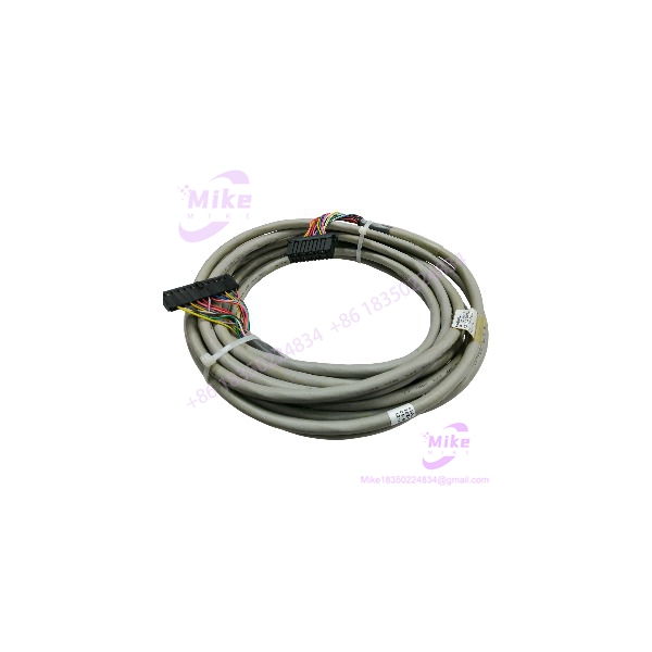
FS-SICC-0001L3
Key Technical Specifications
- Model: FS-SICC-0001/L3
- Manufacturer: Honeywell
- Product Type: System Interconnection Cable
- Application: Safety Manager chassis I/O to FTA
- Cable Family: /Lx
- Specified Length: 3 m
- Conductor Construction: 20 × AWG 22 / 0.34 mm²
- Shielding: Double-shielded
- Nominal Outer Diameter: 9.93 mm / 0.39 in
- Termination: FTA-oriented system interconnection configuration
- System Role: Chassis I/O interconnection
- Related Cable Family: SICP-0001/Lx for chassis I/O terminating on crimp pins
- Electrical Type: Passive interconnection cable; no independent logic execution or firmware
- Typical Installation: Honeywell Safety Manager control cabinet and FTA wiring architecture
The Honeywell reference is particularly useful here because it explicitly separates the SICC and SICP cable families by termination method. That is a better compatibility check than relying on generic descriptions such as “Honeywell Safety Manager cable.”
Global Sourcing & Live-Test SOP
Inbound Verification
For an , QC starts with physical identification rather than electrical assumptions.
Verify:
- Complete marking:
- Cable length: 3 m
- Conductor count and gauge against the approved specification
- Connector/termination style
- Connector keying and mechanical condition
- Jacket condition
- Shield continuity
- Evidence of unauthorized retermination or cable splicing
- Packaging and traceability documentation where supplied
A cable does not contain firmware, so the usual CPU/module firmware check is irrelevant. The equivalent procurement risk is wrong termination, wrong length, damaged shielding, or an incorrectly substituted cable family.
Live Simulation
The preferred test setup is an authenticated Safety Manager test rack with the intended chassis I/O and corresponding FTA arrangement.
Install the exactly as it would be installed in the target architecture. Confirm that every intended I/O path reaches the correct FTA termination point.
Do not simply measure continuity from one connector end to the other and declare the cable good. Continuity testing can identify an open conductor, but it does not prove correct pin assignment, shielding integrity, connector retention, or system-level channel mapping.
Diagnostics
A practical incoming-test sequence should include:
- Point-to-point conductor continuity.
- Conductor-to-conductor isolation check.
- Shield continuity verification.
- Inspection for intermittent opens while gently flexing the cable within approved mechanical limits.
- Connector pin/key inspection.
- Channel-by-channel I/O simulation through the installed cable.
- Verification that the expected field channel changes at the correct FTA point.
For low-level electrical verification, a calibrated Fluke-class multimeter is useful. For the final acceptance test, however, the Safety Manager I/O diagnostic environment provides much more meaningful evidence.
Final Prep
Before shipment:
- Record the exact model and length.
- Photograph both termination ends.
- Record QC results.
- Protect connectors against impact and contamination.
- Package using ESD-conscious handling practices.
- Preserve the cable’s natural routing shape where practical.
Honestly, cable replacement is one of the easiest areas to get wrong because the part looks deceptively simple.
The Field Engineer’s Pitfall Guide
❗ Warning 1 — Do not substitute SICP for SICC merely because both belong to the same Safety Manager family.
Honeywell separates cables terminating on FTAs from SICP-0001/Lx cables terminating on crimp pins. A cable can have the right conductor count and still be the wrong component for the installation.
❗ Warning 2 — Verify the /L3 length before routing the replacement.
The FS-/L3 is specified as a 3-meter version. Cable length affects cabinet routing, connector strain, and whether the cable can reach the intended FTA without excessive mechanical tension. I’ve seen maintenance teams force a nominally similar replacement into a cabinet because the part number looked right, only to discover that the routing created unacceptable connector stress.
❗ Warning 3 — Never assume conductor order from the cable’s physical appearance.
The 20-conductor construction does not give permission to infer pin assignments. Match the installed drawing, connector identification, and approved Safety Manager architecture before moving wires or terminating anything. A continuity test confirms that copper exists; it does not prove that channel 1 is actually reaching the intended field termination.
A damaged shield deserves the same attention. In a cabinet with contactors, motor starters, and other switching equipment nearby, degraded shielding can create intermittent diagnostic behavior that is much harder to reproduce than a clean open circuit.
Intent-Driven FAQ
Is the FS-/L3 a Safety Manager I/O module?
No. The is a system interconnection cable. Its job is to provide the physical electrical connection between Safety Manager chassis I/O and the applicable FTA. Honeywell classifies /Lx under the system interconnection cable section of the Safety Manager hardware reference.
What does the /L3 mean?
It identifies the 3-meter version of the FS- cable family. Published product documentation lists FS-/L3 as a 3 m cable.
Can I use another Honeywell cable with the same number of conductors?
Not automatically. The cable family, termination arrangement, connector keying, length, and approved system drawing all need to match. In particular, Honeywell distinguishes SICC cables from SICP cables based on how they terminate.
Does the FS-/L3 have firmware?
No. It is a passive interconnection cable. There is therefore no firmware revision to upgrade or downgrade. The relevant compatibility controls are mechanical termination, conductor assignment, shielding, cable length, and system architecture.
Can I disconnect the FS-/L3 while the Safety Manager is running?
Do not treat it as an ordinary signal cable that can be unplugged casually. Disconnecting an active chassis-I/O interconnection can interrupt field I/O paths and potentially affect a running safety function. Follow the site’s approved maintenance procedure and determine the consequences for the affected safety loops before removal.
How should a surplus FS-/L3 be tested?
At minimum, verify the exact model and length, inspect both terminations, check conductor continuity and isolation, verify shield continuity, and perform a system-level channel test on an appropriate Safety Manager test rack. A basic ohmmeter check alone is insufficient acceptance evidence for critical replacement stock.
Is the FS-/L3 obsolete?
Do not determine obsolescence from marketplace availability alone. Honeywell’s current published Safety Manager hardware reference still documents the family for chassis I/O-to-FTA connections. For a specific FS-/L3 purchase, verify the required revision, termination configuration, and approved replacement status against the customer’s installed system documentation.





