

Description
Honeywell FC-TSDI-16UNI | 16-Channel Safe Digital Input FTA
Dynamic Product Introduction
A common procurement mistake is to search for the FC-TSDI-16UNI as though it were a 16-channel PLC input card. It is not. The TSDI-16UNI is the field termination side of the Safety Manager architecture: field wiring lands on its screw terminals, while the system interconnection cable carries those signals toward the associated Safety Manager input circuitry.
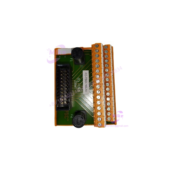
The FC-TSDI-16UNI provides 16 field channels divided into two groups of eight. Each group has a 250 mA fuse in the common positive line. Honeywell specifies the assembly for standard DIN EN rail installation, with a compact 91 mm rail footprint.
The “UNI” designation is important. This is not simply another 24 VDC terminal assembly. Honeywell’s certification documentation describes the TSDI-16UNI as a Safe Digital Input FTA for 24/48 VDC and NAMUR, 16 channels. The actual permissible field voltage is ultimately determined by the input module connected to the FTA, so procurement should not treat the FTA’s insulation/overvoltage ratings as an unrestricted field-signal operating range.
FC-TSDI-16UNI
Key Technical Specifications
- Manufacturer: Honeywell
- Model: FC-TSDI-16UNI
- Product Type: Safe Digital Input Field Termination Assembly
- System: Honeywell Safety Manager
- Channels: 16
- Channel Arrangement: 2 groups of 8
- Signal Application: 24/48 VDC and NAMUR, subject to the connected input module
- Maximum Voltage Rating: 50 VDC under IEC 61010-1 overvoltage Category III conditions; 150 VDC under Category II conditions
- Actual Maximum Field Voltage: Defined by the connected input module
- Group Protection: 250 mA fuse in each common positive line
- Fuse Size: 5 × 20 mm
- Fuse Voltage Rating: 400 VAC / 400 VDC
- Maximum Output Current per Fuse: 175 mA
- Module Dimensions: 90 × 70 × 60 mm
- DIN Rail: TS32 / TS35 × 7.5
- Used Rail Length: 91 mm
- Field Termination: Screw terminals
- Maximum Wire Diameter: 2.5 mm² / AWG 14
- Strip Length: 7 mm
- Terminal Tightening Torque: 0.5 Nm
- Approvals Listed by Honeywell: CE, TUV, UL, CSA, FM
- Coating: Conformal-coated FC version
These values come primarily from Honeywell’s Safety Manager Hardware Reference. The certification release list independently identifies the FC version as part number 3440741, with the description “Safe Digital Input FTA (24/48Vdc, NAMUR 16 channels) (conformal coated).”
System Architecture and Compatibility
The FC- should be evaluated as part of the complete Safety Manager signal path rather than as an independent I/O card.
A typical architecture is:
Field device → FC- → SICC-0001/Lx system interconnection → associated Safety Manager input module
Honeywell documentation describes the as the interface between the system interconnection cable and external field wiring. Technical documentation also associates the with SDIL-1608 input modules, including redundant configurations.
That distinction matters during replacement. A physically identical-looking terminal assembly does not automatically make a valid substitute. The field wiring, interconnection cable, input module, channel configuration, fuse arrangement, and Safety Manager hardware revision all need to agree.
Global Sourcing & Live-Test SOP
Inbound Verification
- Confirm the faceplate marking reads rather than FS-.
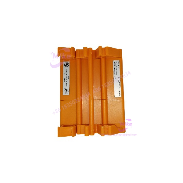
- Verify the OEM label, catalog/part number, revision information, and serial/traceability markings where present.
- Check the conformal coating and PCB condition if the housing allows inspection.
- Inspect both fuse positions and the screw-terminal assembly for damage or corrosion.
- Confirm that the supplied item is actually the FTA; do not substitute a similarly numbered Safety Manager I/O module.
Honeywell distinguishes FC hardware from FS hardware by coating. For this family, FC- is the conformal-coated version.
Live Simulation
Do not validate the FC- as a standalone PLC input card.
A meaningful functional test requires the appropriate Safety Manager interconnection hardware and compatible input module. Verify channel continuity from field terminal through the FTA and system interconnection path to the intended input channel.
For a NAMUR application, use the correct NAMUR-compatible test arrangement rather than applying arbitrary voltage levels to the field terminals.
Diagnostics and Wiring Verification
Check:
- All 16 terminal positions for continuity and correct channel mapping.
- Both common-positive fuse circuits.
- Correct fuse rating.
- SICC interconnection integrity.
- Channel-to-channel isolation where required.
- Input indication and diagnostics at the associated Safety Manager input module.
- Correct response of the configured field input device.
A continuity check alone is not enough. An FTA can pass a simple wire test while still being incorrectly matched to the connected Safety Manager input hardware.
Final Preparation
Record:
- Exact model:
- Hardware/revision marking
- Condition of both fuses
- Test configuration used
- Verified channels
- Any replacement terminal hardware supplied with the unit
Package the assembly in ESD-safe protective material with the terminal area protected from mechanical impact.
Field Engineer’s Pitfall Guide
❗ Do not confuse the FTA with the input module.
The FC- terminates field wiring. It is not the processor that interprets the digital signal. Buying a “16-channel digital input module” based only on channel count can result in the wrong hardware entirely.
This is especially important when comparing it with FC-SDIL-1608. The two components serve different positions in the Safety Manager signal path.
❗ Do not assume “UNI” means unlimited voltage compatibility.
Honeywell’s documentation gives the FTA’s maximum voltage ratings, but explicitly states that the actual maximum voltage is defined by the connected input module. The certification description identifies the application as 24/48 VDC and NAMUR. Verify the complete input chain before applying field power.
❗ Do not overlook the two fused groups.
The 16 channels are divided into two groups of eight, with a 250 mA fuse in each common-positive line. A field wiring problem can therefore produce symptoms affecting a group rather than a single channel. The fuse specification is 250 mA, with a maximum output current per fuse specified at 175 mA.
Intent-Driven FAQ
Is Honeywell FC- a digital input module?
No. It is a Safe Digital Input Field Termination Assembly (FTA). Its job is to provide the field wiring interface for the associated Safety Manager input architecture.
How many channels does FC- support?
It supports 16 channels, organized as two groups of eight.
What signals does FC- support?
The Safety Manager certification documentation identifies the as a Safe Digital Input FTA for 24/48 VDC and NAMUR, 16 channels. The precise allowable operating range must be checked against the connected input module.
What is the difference between FC- and FS-?
Both are variants. The FC version is conformal-coated, while the FS version is the non-conformal-coated version.
What fuse does FC- use?
Honeywell specifies a 250 mA fuse, 5 × 20 mm, with 400 VAC and 400 VDC voltage ratings. Each of the two eight-channel groups has its own common-positive fuse.
What DIN rail does FC- use?
The assembly supports TS32 and TS35 × 7.5 DIN EN rails and occupies approximately 91 mm of rail length.
What should I verify before replacing an FC-?
Verify the exact part number and FC coating version, the associated Safety Manager input module, SICC interconnection cable, field signal type, channel mapping, fuse arrangement, and hardware revision. Do not approve a replacement based on physical appearance or channel count alone.





