

Description
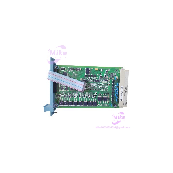
Honeywell FC-SDO-0824 | 8-Channel Safe Digital Output Module
Dynamic Product Introduction
The FC-SDO-0824 is best understood as a safety output interface, not simply an eight-channel 24 VDC transistor card. It is designed to drive field loads from the Honeywell Safety Manager platform while incorporating output diagnostics and secondary means of de-energization into the safety architecture.
Honeywell specifies eight 24 VDC solid-state source outputs, each with a maximum current of 550 mA and short-circuit protection. The hardware reference also specifies less than 2.0 VDC voltage drop at 500 mA, less than 0.1 mA off-current, and a maximum load capacitance of 1 µF.
That distinction matters when the connected load is a solenoid, contactor interface, annunciator, or other shutdown-related device. The output rating alone does not establish whether a particular field load is acceptable. Coil characteristics, inrush, suppression, wiring resistance, ambient temperature, and the associated Field Termination Assembly all need to be checked.
The SDO-0824 architecture divides the eight outputs into two groups of four. The safety design includes a secondary means of de-energizing outputs, allowing the watchdog/processor path to remove output power independently of the application command. The module also performs diagnostics associated with de-energization capability, output-group shutdown, output crosstalk, and suppression-diode operation.
For procurement, the FC designation should not be ignored. Honeywell uses FC for conformal-coated products, so FC-SDO-0824 should be matched against the installed system bill of material rather than substituted merely because another SDO-0824 variant has the same channel count.
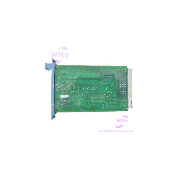
FC-SDO-0824
Key Technical Specifications
- Manufacturer: Honeywell
- Model: FC-SDO-0824
- Product Type: Safe Digital Output Module
- System: Honeywell Safety Manager
- Output Channels: 8
- Output Type: 24 VDC solid-state source
- Output Protection: Short-circuit proof
- Maximum Output Current: 550 mA per channel
- Maximum Lamp Load: 120 mA / 2.9 W
- Maximum Load Capacitance: 1 µF
- Voltage Drop: <2.0 VDC at 500 mA
- Off Current: <0.1 mA
- WDG Input Current: 8 mA
- 5 VDC Supply Requirement: 25 mA
- 24 VDC Internal Supply: 25 mA
- 24 VDC External Supply: 70 mA, without output load
- Mechanical Space: 4 TE × 3 HE, equivalent to 4 HP × 3U
- Key Coding: Module holes A9, C9; chassis large pins A9, C9
- Approvals: CE, TÜV, UL, CSA, FM
Output Loading Matters
The headline figure is 550 mA, but it should not be interpreted as an unrestricted 550 mA continuous load under every operating condition.
Honeywell’s documentation includes a load-versus-temperature relationship. The published technical data specifies the 550 mA maximum, while the module’s allowable output loading must be evaluated against operating temperature and the actual field load.
For inductive loads, the architecture also incorporates suppression-diode functionality. That is particularly relevant when driving solenoid-type loads; the suppression arrangement should be considered part of the qualified field-load design rather than treated as an optional accessory.
Global Sourcing & Live-Test SOP
1. Inbound Verification
For FC-, receiving inspection should capture:
- Exact marking
- Hardware revision
- Part number
- Serial number
- Conformal-coating condition
- Connector and keying condition
- Housing damage
- Evidence of corrosion or contamination
- Previous installation evidence
The FC versus FS designation deserves a specific inventory check. Honeywell lists both FS- and FC- as type numbers, and the FC prefix identifies the conformal-coated product family.
2. Live Simulation
Testing should be performed in an authentic Honeywell Safety Manager test environment appropriate to the target installation.
A practical acceptance sequence is:
- Install the module in the correct Safety Manager I/O architecture.
- Verify module initialization and diagnostics.
- Exercise each output individually.
- Verify 24 VDC output behavior under a representative load.
- Check output voltage drop under controlled loading.
- Test short-circuit protection using the approved test procedure.
- Verify output de-energization.
- Verify secondary shutdown/SMOD behavior where supported by the test configuration.
- Check both output groups.
- Record diagnostic status and event information.
Do not connect an unknown high-current solenoid directly to a newly received module simply to see whether it “works.” The load itself can damage the test setup or produce misleading results.
3. Diagnostics
The acceptance record should include:
- Module initialization
- Output state recognition
- Channel-by-channel switching
- Output voltage
- Representative load current
- Short-circuit protection response
- De-energization test
- Group-level shutdown behavior
- Diagnostic/event status
- Safety Manager application recognition
Honeywell’s documentation describes diagnostic checks for the ability to de-energize, secondary group de-energization, output crosstalk, and suppression-diode functionality.
4. Final Preparation
After testing:
- Photograph the identification label.
- Record hardware revision.
- Record serial number.
- Record the Safety Manager release used for testing.
- Record the test load and measured current.
- Package using ESD-safe material.
- Protect the field connector.
- Keep FC- segregated from FS- inventory.
For a safety-system spare, “tested” should mean tested against a defined configuration, not simply powered on.
Field Engineer’s Pitfall Guide
❗ 1. Do Not Treat 550 mA as a Universal Continuous Rating
The 550 mA specification is the maximum output-current figure in Honeywell’s technical data. Actual permissible loading depends on operating conditions and the connected load. Honeywell provides load/temperature information for the architecture.
A field engineer replacing a smaller output module once used the nominal current rating alone to approve a solenoid load. The safer approach is to calculate the actual coil current, startup behavior, temperature conditions, wiring losses, and suppression requirements before commissioning.
❗ 2. Do Not Confuse the With a Generic Transistor Output Card
The FC- is part of the Honeywell Safety Manager safety I/O architecture.
Its output diagnostics and secondary de-energization path are significant. The module is not equivalent simply because another PLC card also provides eight 24 VDC transistor outputs.
Honeywell’s documentation specifically describes secondary de-energization and diagnostic tests associated with the .
❗ 3. Verify the FTA and Wiring Before Applying Field Power
The does not exist in isolation. Honeywell documents dedicated safe digital output termination assemblies, including the TSDO-0824 family, for interfacing the Safety Manager system interconnection to external field wiring.
Before replacement, compare the existing termination arrangement, output polarity, external 24 VDC supply, channel assignment, and application configuration. A correctly identified output module can still be installed into an incorrectly prepared field circuit.
Intent-Driven FAQ
What is Honeywell FC-?
FC- is an 8-channel Safe Digital Output Module for Honeywell Safety Manager. It provides 24 VDC solid-state source outputs with short-circuit protection.
How many outputs does FC- have?
It has 8 output channels. Each output is a 24 VDC solid-state source, with a specified maximum current of 550 mA.
Is FC- a 24 VDC output module?
Yes. Honeywell specifies the output as a 24 VDC solid-state source. The output is short-circuit proof and has a specified maximum current of 550 mA.
Can FC- drive solenoid valves?
The architecture is designed to drive field loads, including inductive loads, but the specific solenoid must be checked against the module’s current, load, capacitance, temperature, wiring, and suppression requirements. The documentation includes suppression-diode functionality for inductive loads.
What is the difference between FC- and FS-?
Honeywell identifies both as type numbers. The FC prefix denotes the conformal-coated version, while FS identifies the non-conformal-coated version.
What is the maximum load capacitance?
Honeywell specifies a maximum load capacitance of 1 µF for the output.





