

Description
Honeywell FC-IOCHAS-0002R | 18-Module Redundant I/O Rack
Dynamic Product Introduction
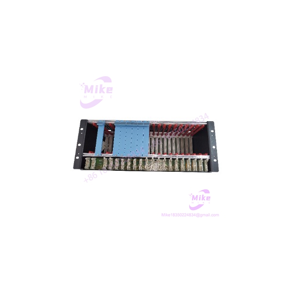
When a Safety Manager installation has to maintain I/O redundancy, the chassis is part of the control architecture—not just a metal enclosure. The Honeywell FC-IOCHAS-0002R is specifically designed for Safety Manager A.R.T. redundant I/O and provides the 19-inch housing and associated infrastructure for up to nine pairs of redundant I/O modules. Honeywell specifies 21 module positions, with slots 1 through 18 allocated to I/O modules in redundant pairs.
The architecture is deliberately divided by function. Slots 1–18 accommodate the redundant I/O population, while slot 19 sits behind the blind front and contains the horizontal I/O bus transfer hardware. Slots 20 and 21 are dedicated to the IO-0002 extender modules. This is why replacing FC-IOCHAS-0002R with a visually similar 19-inch chassis is not a sensible migration strategy: the electrical backplane, I/O bus, module pairing, and extender arrangement are integral to the Safety Manager system.
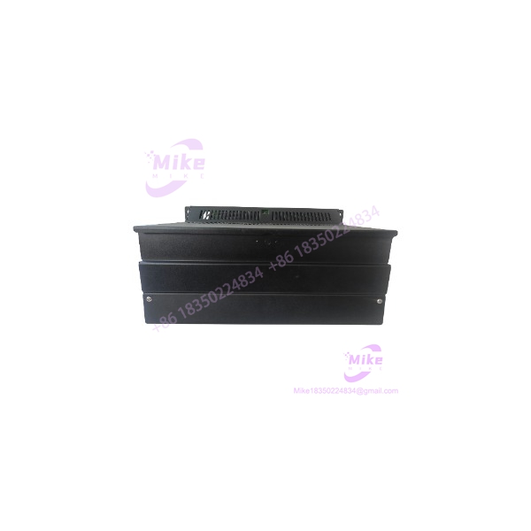
Honeywell’s hardware reference identifies the IOCHAS-0002R housing as a purpose-built Safety Manager enclosure. The front cover protects the I/O flat cables and can be swung upward for access, while the rear I/O cover can be removed for service access to the chassis hardware.
FC-IOCHAS-0002R
Key Technical Specifications
- Manufacturer: Honeywell
- Part Number: FC-IOCHAS-0002R
- System: Honeywell Safety Manager A.R.T.
- Chassis Type: Redundant I/O chassis
- Rack Format: 19-inch
- Total Slots: 21
- Slot Width: 4 TE per module position
- I/O Module Positions: Slots 1–18
- Redundancy Arrangement: Slots 1–18 configured as 9 redundant pairs
- Slot 19: Dedicated location behind the blind front for the horizontal I/O bus transfer board
- Slots 20–21: Dedicated to IO-0002 I/O extender modules
- I/O Backplane: FS-IOB-0002R
- Horizontal I/O Bus Backplane: FS-IOBUS-HB2R
- Bus Transfer Board: FC-IOBUS-HB2A
- I/O Extenders: 2 × FC-IO-0002
- Front Access: Swing-up cover for I/O flat-cable access
- Rear Access: Removable I/O back cover
- Application: Redundant Safety Manager I/O installations
Chassis Architecture
The FC-IOCHAS-0002R should be understood as a system assembly rather than a simple passive rack. Honeywell’s documented component breakdown includes:
- 1 × I/O housing
- 1 × FS-IOB-0002R redundant I/O backplane
- 2 × FC-IO-0002 I/O extender modules
- 1 × FS-IOBUS-HB2R horizontal I/O bus backplane
- 1 × FC-IOBUS-HB2A horizontal I/O bus transfer board
- 1 × blind front at slot 19
This component relationship is important when purchasing a replacement chassis. An “empty chassis” and a complete FC- assembly are not necessarily the same procurement item.
Global Sourcing & Live-Test SOP
Inbound Verification
Start with the complete identification and then verify the physical architecture.
Check:
- Honeywell part number and identification
- 19-inch mechanical housing
- 21 slot positions
- Slot numbering and mechanical integrity
- Front swing-up cover and locking mechanism
- Rear I/O cover and locking screw
- Backplane connectors
- I/O extender positions
- Horizontal bus interface
- Flat-cable interfaces
- Evidence of corrosion, bent connectors, impact damage, or cabinet contamination
For a used or surplus chassis, inspect the backplane much more carefully than the sheet-metal enclosure. The enclosure can look excellent while a connector or backplane has suffered years of insertion cycles.
Live Simulation
A chassis-only bench test has limited value because the FC- is infrastructure for the Safety Manager I/O system.
A meaningful verification should use an authentic Safety Manager A.R.T. test configuration:
- Install the appropriate redundant I/O modules in paired positions.
- Verify the IO-0002 extender modules in slots 20 and 21.
- Verify the slot-19 bus-transfer arrangement.
- Connect the appropriate horizontal I/O bus.
- Power the chassis according to the installed system configuration.
- Establish communication with the Control Processors.
- Confirm recognition of both redundant I/O paths.
- Exercise representative I/O channels and verify diagnostics.
The objective is not merely to prove that the chassis accepts modules. The objective is to prove backplane continuity, redundant bus communication, module recognition, and correct I/O addressing.
Diagnostics
If an installed I/O pair fails to communicate, troubleshoot the architecture in layers:
I/O module → chassis connector → I/O backplane → horizontal bus → IO extender → Control Processor.
Do not immediately blame the I/O module.
If an entire group of modules disappears together, suspect the common chassis/backplane/bus path before replacing individual field modules. This is one of the more useful distinctions when troubleshooting redundant Safety Manager hardware.
Final Preparation
For maintenance-stock release, record:
- Exact FC- identification
- Physical chassis condition
- Backplane condition
- Connector condition
- Included extender modules
- Included bus-transfer hardware
- Functional test configuration
- Redundant I/O communication result
- Date of inspection
Protect all exposed connectors and flat-cable interfaces during shipment. A chassis can survive normal mechanical handling while its exposed high-density connectors do not.
Field Engineer’s Pitfall Guide
❗ Do not buy the chassis based on the 19-inch dimension alone
A standard 19-inch rack may physically fit into a cabinet and still be completely unsuitable for Safety Manager.
The FC- contains a dedicated Safety Manager I/O backplane and horizontal I/O-bus infrastructure. The mechanical rack dimension is only one part of the compatibility equation.
❗ Do not confuse FC- with a non-redundant I/O chassis
The “0002R” configuration is specifically associated with redundant I/O. Honeywell documents slots 1–18 as paired positions for redundant I/O modules. The chassis also uses dedicated IO-0002 extenders in slots 20 and 21.
If the installed system is built around redundant I/O, substituting a visually similar non-redundant chassis can turn a simple maintenance replacement into a cabinet redesign.
❗ Verify what is actually included in the purchased assembly
This is particularly important in the surplus market.
Honeywell’s documentation describes FC- as a chassis assembly with associated backplane, bus, transfer-board, and extender components. A listing may nevertheless be sold as a housing-only item or with some internal hardware removed.
Before procurement, verify whether the quoted assembly actually contains:
- I/O backplane
- Horizontal I/O bus hardware
- Slot-19 transfer board
- Both IO-0002 extenders
- Blind front
- Required covers
The exact bill of material should be confirmed against the intended replacement scope.
Intent-Driven FAQ
What is Honeywell FC-?
FC- is a 19-inch redundant I/O chassis for Honeywell Safety Manager A.R.T. It provides the physical and electrical infrastructure for redundant Safety Manager I/O modules.
How many I/O modules can FC- hold?
Honeywell specifies 18 I/O module positions in slots 1–18, arranged as nine redundant pairs. Slots 20 and 21 are reserved for the IO-0002 extender modules, while slot 19 is associated with the bus-transfer hardware.
Is FC- just an empty rack?
Not necessarily. Honeywell’s documented FC- component set includes the I/O housing, redundant I/O backplane, two IO-0002 extenders, horizontal I/O bus backplane, bus-transfer board, and blind front. However, individual surplus listings can have different included components, so the actual bill of material must be checked before purchase.
What system uses FC-?
It is designed for the Honeywell Safety Manager A.R.T. redundant I/O architecture. It is not a generic PLC rack or universal DCS I/O chassis.
What is installed in slots 20 and 21?
Honeywell documents IO-0002 I/O extender modules in slots 20 and 21. These provide the interface between the Safety Manager control side and the chassis I/O-bus architecture.





