


Description
Honeywell 51309218-175 | MC-TAMR03 Interface Board, New Surplus
Architect’s Product Breakdown
The Honeywell 51309218-175, widely recognized by its module designation MC-TAMR03, operates as an essential interface bridge within Honeywell’s legacy TotalPlant Solution (TPS) and TDC 3000 processing environments. Its primary responsibility involves routing, isolating, and translating process control signals between field termination assemblies and the central controller backplane. Maintaining signal fidelity through this board is critical for preventing process variable distortion in continuous production architectures.
Deploying or replacing this module requires strict attention to chassis slot assignment and system grounding parameters. Instrumentation engineers must ensure that all incoming multi-pin interface cables are securely fastened and free of mechanical strain, as micro-vibrations in heavy industrial enclosures can degrade connection integrity over time. Verifying firmware and hardware revision compatibility before integration prevents unhandled bus arbitration exceptions during node startup.
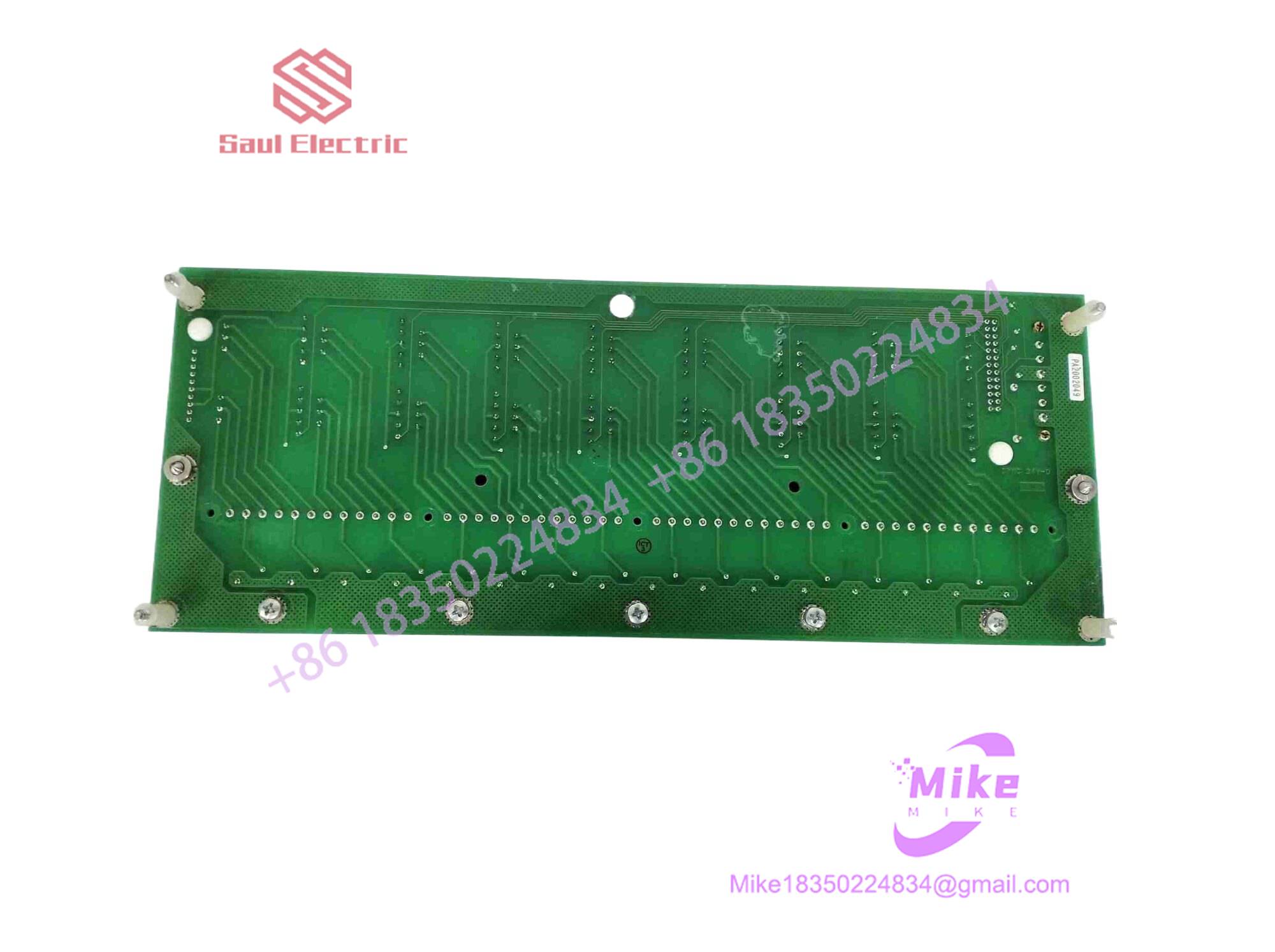
51309218-175
Key Technical Specifications
| Parameter | Specification |
| Manufacturer | Honeywell |
| Part Number | 51309218-175 |
| Module Designation | MC-TAMR03 |
| Module Type | Bus Interface / Control Module |
| Compatible Architecture | Honeywell TPS / TDC 3000 Systems |
| Mounting Type | Rack Chassis Slot Insertion |
| Operating Temperature | 0°C to +60°C |
| Storage Temperature | -40°C to +85°C |
| Relative Humidity | 5% to 95% non-condensing |
| Approx. Weight | 1.2 kg |
Field Engineer’s Pitfall Guide (Unique Value)
- Backplane Pin Alignment: Forcing this module into a chassis slot without proper alignment can bend delicate backplane pins, resulting in intermittent communication timeouts that are exceptionally difficult to isolate.
- Shielding and Ground Disconnects: Leaving the interface cable shield ungrounded at the cabinet chassis introduces high-frequency electromagnetic interference, leading to erratic signal readings across connected loops.
- Electrostatic Discharge Vulnerability: The onboard integrated circuits are sensitive to static electricity. I once watched an instrument technician handle a replacement board without an ESD wrist strap in a dry control room, instantly frying an input transceiver and delaying plant startup by a full shift.
QA & Testing SOP (Transparency)
- Visual & Origin Verification: Units undergo microscopic inspection for authentic OEM branding, solder joint integrity, and uncompromised gold edge fingers.
- Test Bench Simulation: The board is mounted into a dedicated TPS test rack, undergoing continuous power-on cycles to verify thermal stability and rail voltage rigidity.
- Signal Handshake Validation: Automated test rigs inject calibrated signals and verify communication handshakes, register scaling, and diagnostic LED responses.
- Anti-Static Packaging: Post-testing, units are sealed in multi-layer moisture-barrier static-shielding bags with high-density foam padding to prevent transit damage.
Technical FAQ
- Can I hot-swap this interface module while the process is running? No. Always de-energize the rack and isolate local power feeds before extracting or inserting this card to prevent electrical arcing and backplane bus corruption.
- Does this module store configuration parameters locally? System logic and configuration parameters are handled by the primary node controller, though minor hardware routing registers reside on the board itself.
- What causes communication dropouts immediately after installation? This is typically driven by an incomplete seating of the edge connector, a loose wiring harness, or an unacknowledged hardware configuration mismatch in the system database.
- What warranty is provided with a surplus unit? Units carry a standard 12-month replacement warranty backed by comprehensive bench testing.





