

Description
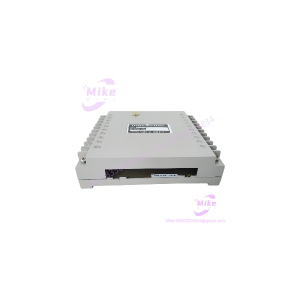
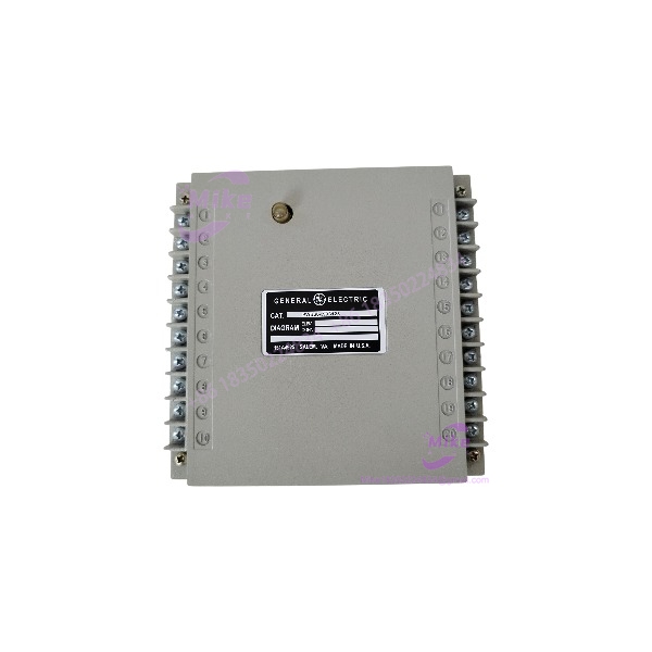
GE PWB68A993125 | Speedtronic Mark II SCR Gate & Filter Card
Dynamic Product Introduction
In legacy power generation plants running GE Speedtronic turbine control platforms, managing high-power thyristor bridge firing without introducing cross-talk noise to sensitive control electronics is crucial to plant stability. Stray high-frequency noise or weak trigger pulses on an SCR bridge can cause incomplete phase conduction, leading to fuel valve jitter or excitation imbalance on massive steam and gas turbine generators. The General Electric PWB68A993125 SCR Gate & Filter Card acts as a dedicated firing interface built specifically for these high-stress power stage environments.
Engineered with onboard LC filter networks, the PWB68A993125 strips out EMI and RFI noise generated by adjacent switching hardware before shaping and dispatching precise gate firing pulses. (Honestly, maintaining clean firing pulses under noisy power house line conditions prevents sudden valve hunting that can force an unexpected load reduction or trip.) Constructed with heavy-duty PCB traces and screw terminal contacts, the card ensures robust physical signal retention—though keeping the board clean from carbon dust and oil mist buildup remains vital for maintaining its high dielectric isolation ratings.
PWB68A993125
Key Technical Specifications
- Manufacturer & Platform: General Electric (GE) / Speedtronic Mark II Series
- Part Number Variations: PWB68A993125 / 68A993125 / PWB68A993125-S
- Module Type: SCR Gate Driver & LC Filter Circuit Board
- Input Power Requirement: 24 VDC nominal control voltage (\pm 10\%)
- Output Trigger Signals: Galvanically isolated SCR gate drive firing pulses
- Filtering Architecture: Integrated LC low-pass filter array for EMI/RFI suppression
- Channel Isolation: 1500 VDC isolation rating between gate output channels and logic ground
- Terminal Interface: Board-mounted screw terminal blocks / backplane edge contacts
- Operating Ambient Temperature: -40^\circC to +70^\circC (-40^\circF to +158^\circF)
- Dimensions & Weight: Approximately 22.8 cm \times 15.2 cm \times 3.2 cm (9″ \times 6″ \times 1.25″), 0.65 kg (1.43 lbs)
Global Sourcing & Live-Test SOP (Transparency Core)
Sourcing legacy Speedtronic and GE power electronics cards requires rigorous bench qualification to guarantee circuit health before installation into active turbine governor loops. Every PWB68A993125 card entering inventory undergoes a comprehensive five-stage testing protocol:
- Inbound Inspection: Printed silk-screen part numbers, trace layers, and resistor network values are checked against original GE engineering schematics. We inspect board traces for copper lifting, verify screw terminal threads, and check filter capacitors for dielectric leakage or swelling.
- Live Bench Test Setup: The PWB68A993125 is mounted into a specialized GE Speedtronic test fixture supplied with regulated 24 VDC logic power and linked to a dummy thyristor load bank.
- Diagnostics & Waveform Analysis: High-speed drive pulses are commanded across all gate output channels. Using a 4-channel digital oscilloscope, we analyze pulse rise times, peak voltage amplitudes, and pulse duration to confirm clean firing signals without ringing or phase distortion.
- Isolation & Noise Suppression Verification: High-voltage insulation testing (1500 VDC) is performed across output channels. A high-frequency signal generator injects simulated industrial noise onto the input lines to verify that onboard LC filters attenuate noise spikes below threshold levels.
- Final Prep: Terminal contact pins are cleaned with electronic solvent, protective conformal coating integrity is inspected, and the PWB68A993125 card is vacuum-sealed in heavy-duty anti-static moisture-barrier packaging.
The Field Engineer’s Pitfall Guide
❗ Loose Screw Terminal Torque Leading to Thermal Oxidation: When field wiring the SCR gate output cables to the terminal strip of the PWB68A993125, loose terminal screws create high contact resistance. Under high pulse current demands, this resistance generates localized heat, oxidizing terminal leads and eventually causing intermittent firing failures that throw thyristor bridge imbalance alarms.
❗ Unshielded Gate Drive Wiring in High-EMI Trays:Never route the gate firing leads originating from the PWB68A993125 in parallel with high-voltage AC power lines without using twisted-pair shielded cables grounded at a single chassis point. Induced noise on unshielded gate leads can falsely trigger sensitive SCRs, creating dangerous shoot-through conditions in power bridge circuits.
❗ Hot-Swapping Without Auxiliary Power Isolation: While the module resides in a low-voltage rack, pulling or seating the PWB68A993125 while 24 VDC auxiliary or high-voltage power is present on the thyristor bridge can result in transient voltage spikes across unseated gate terminals, potentially damaging the internal driver transistors or causing an unexpected valve solenoid movement.
Intent-Driven FAQ
Q: What is the primary operational role of the GE PWB68A993125 card? The PWB68A993125 functions as an SCR gate drive pulse generator and signal filter card. It receives low-level control timing signals from the central turbine governor and converts them into high-energy, noise-filtered firing pulses that trigger high-power thyristors used in fuel valve actuators or excitation systems.
Q: Are the PWB68A993125 and PWB68A993124 cards interchangeable? While both belong to the same GE 68A993 series circuit board family, minor differences in filter component values, jumper layouts, or channel counts can exist between sub-suffix revisions. Always verify circuit schematics and physical channel layout before substituting a 3124 card for a 3125.
Q: What indicates an internal component failure on a field-installed PWB68A993125 card? Symptoms include erratic fuel valve operation, phase-imbalance fault alarms on the thyristor drive rack, or missing pulse signals during startup. Disconnecting power and measuring resistance across gate-to-cathode output channels can reveal shorted driver transistors or open filter resistors.
Q: Does the PWB68A993125 require any software programming or firmware flashing? No. The PWB68A993125 is a pure analog hardware circuit board consisting of discrete pulse-shaping components, filter networks, and isolation stages. It operates entirely based on incoming hardware signals and requires no software or firmware loading.
Q: How do I test the internal LC filter networks on a spare PWB68A993125 card? Using an LCR meter, test the inductors and capacitors in the filter section for out-of-tolerance values or open circuits. Alternatively, inject a high-frequency AC sweep signal across the input terminals and measure signal attenuation on the output to confirm proper filtering performance.





