

Description
GE IS220PDIOH1B | Mark VIe Discrete I/O Pack
Product Introduction
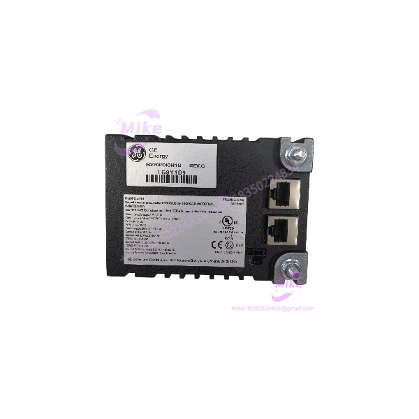
When a Mark VIe discrete I/O pack is replaced, the terminal board is just as important as the pack itself. The GE IS220PDIOH1B is a PDIO discrete input/output pack designed to interface field wiring with one or two I/O Ethernet networks. It combines a local processor with acquisition electronics and supports both discrete input monitoring and relay output control.
GE’s Mark VIe system guide specifies capacity for up to 24 contact inputs and 12 relay outputs. The pack is used with compatible TDBS or TDBT terminal-board variants, and the terminal board determines the applicable field-voltage capability. GE documentation lists specific H1B/terminal-board combinations approved for hazardous locations, making exact hardware matching especially important for replacement work.
For procurement, the IS220PDIOH1B should be treated as a configuration-specific turbine-control component. Verify the exact terminal-board model, wiring arrangement, and approved system configuration before representing the unit as a drop-in replacement.
IS220PDIOH1B
Key Technical Specifications
- Manufacturer: General Electric
- Model: IS220PDIOH1B
- Functional Acronym: PDIO
- Series: Mark VIe / Mark VIeS
- Module Type: Discrete Input/Output I/O Pack
- Input Capacity: Up to 24 contact inputs
- Output Capacity: Up to 12 relay outputs
- Power Supply Voltage: 27.4–28.6 VDC
- Nominal Supply Voltage: 28.0 VDC
- Maximum Supply Current: 0.81 A DC
- Contact Input Voltage: 0–32 VDC
- Contact Output Voltage: Up to 32 VDC
- Contact Output Current: Up to 3.15 A, subject to applicable output and terminal-board limitations
- Contact-Wetting Outputs: Terminal-board dependent; documented wetting-output limits differ by TDBS/TDBT variant
- Ethernet Interface: Two RJ-45 Ethernet ports
- Internal Architecture: Local processor and discrete I/O acquisition board
- Terminal Board Compatibility: ISx0yTDBSH2A, ISx0yTDBSH8A, ISx0yTDBTH2A, or ISx0yTDBTH8A, as applicable
- Diagnostics: Ethernet, power, attention, and relay-related LED indications
- Installation: Mark VIe distributed I/O terminal-board assembly
The electrical values above are drawn from GE Mark VIe system documentation. Actual field wiring limits, contact-wetting characteristics, and hazardous-location approval depend on the associated terminal board and approved assembly combination. Verify the relevant GE manual and terminal-board model before applying field power.
Global Sourcing & Live-Test SOP
For a used or surplus GE IS220PDIOH1B, a power-up check alone is not enough. Verify the complete I/O assembly and test the functions relevant to the intended application.
1. Inbound Verification
- Photograph the complete GE nameplate and all board markings.
- Confirm the exact IS220PDIOH1B part number.
- Record serial number, revision, and assembly identifiers.
- Inspect the housing, connectors, Ethernet ports, and terminal-board interface.
- Check for corrosion, contamination, heat discoloration, or evidence of prior repair.
- Inspect connector contacts for bending, oxidation, or mechanical damage.
- Confirm whether the terminal board is included or sold separately.
- Compare the supplied unit with the customer’s original pack and terminal-board configuration.
2. Terminal Board and Configuration Review
- Identify the associated TDBS or TDBT terminal-board model.
- Confirm that the terminal board is an approved match for the H1B pack.
- Verify the installed field-voltage and contact-wetting arrangement.
- Check the system’s intended I/O configuration and network architecture.
- Confirm hazardous-location requirements where applicable.
- Do not assume that a terminal board used with a PDIOH1A is automatically approved for the H1B variant.
3. Controlled Power-Up and I/O Simulation
Use an appropriate GE-compatible test setup and qualified personnel.
- Inspect the pack and terminal-board interface before energizing.
- Confirm the specified 28 VDC supply arrangement.
- Monitor startup and available diagnostic LEDs.
- Verify Ethernet link and communication behavior using a suitable test network.
- Simulate contact inputs within the documented limits.
- Test relay outputs with appropriate, current-limited test loads.
- Confirm input and output status through the applicable controller or test software.
- Record the test setup, observed values, and any fault indications.
Do not apply field voltage or relay loads based solely on a generic PDIO-family description. Follow the applicable GE wiring and test documentation.
4. Extended Run and Diagnostics
Where suitable test equipment is available, conduct an extended powered run appropriate to the intended application.
Monitor:
- Power-supply stability
- Ethernet link and communication
- Contact input response
- Relay output switching
- Diagnostic indications
- Unexpected resets
- Abnormal heating
- Terminal-board and connector integrity
Record the test duration, associated terminal board, applied supply, test results, and observed faults. Do not advertise a unit as fully tested unless the actual test scope supports that claim.
5. Final Preparation
- Record the complete model, revision, and serial number.
- Photograph the I/O pack and any included terminal board.
- Preserve available inspection and test records.
- Use ESD-safe packaging.
- Protect Ethernet ports and board connectors from impact.
- Clearly disclose whether the unit is new surplus, used, refurbished, tested, or untested.
- State whether the terminal board is included or sold separately.
Field Engineer’s Pitfall Guide
❗ H1B terminal-board combinations matter
GE lists specific TDBS/TDBT accessory terminal boards for the , including H2A and H8A variants. Do not assume every PDIO terminal board is compatible or approved for the same hazardous-location application. Match the full terminal-board number against the applicable GE documentation.
❗ The terminal board determines field-voltage capability
The PDIO pack’s contact-input and output capabilities are not a blanket authorization to apply any industrial field voltage. Field-voltage capability and contact-wetting behavior depend on the terminal board. Verify wiring, ratings, and terminal assignments before commissioning.
❗ Do not treat an LED power-up as proof of I/O functionality
The includes processor and acquisition electronics. A normal power indication does not prove that all input channels, relay outputs, or Ethernet communications are functional. Test the required I/O paths using a suitable setup before declaring the pack ready for service.
Intent-Driven FAQ
What is the GE ?
The is a GE Mark VIe/Mark VIeS PDIO discrete I/O pack. It interfaces contact inputs and relay outputs with the turbine-control system.
How many inputs and outputs does the support?
GE documentation specifies up to 24 contact inputs and 12 relay outputs. Actual field wiring and output capability depend on the associated terminal board and system configuration.
What power supply does the require?
The specified supply range is 27.4–28.6 VDC, with a nominal rating of 28.0 VDC. Confirm the supply arrangement and wiring against the applicable GE documentation before energizing.
Which terminal boards are compatible with the ?
GE documentation lists compatible H1B combinations including ISx0yTDBSH2A, ISx0yTDBSH8A, ISx0yTDBTH2A, and ISx0yTDBTH8A. Confirm the exact terminal-board model and approved application before replacement.
Is the suitable for hazardous locations?
GE documents approved hazardous-location combinations for the H1B pack with specified terminal boards. Approval applies to the documented combination and installation conditions—not automatically to every possible pack/terminal-board pairing.
Is the hot-swappable?
Do not assume it is hot-swappable. Follow GE and site-specific maintenance procedures for the installed Mark VIe configuration, including any required isolation and commissioning steps.
What should I verify before purchasing?
Confirm the complete model, board revision, terminal-board compatibility, physical condition, included accessories, and test status. Request clear nameplate and connector photographs. For a production turbine, verify the replacement against the approved I/O configuration before ordering.
Bottom Line for Buyers
The is a Mark VIe discrete I/O pack supporting up to 24 contact inputs and 12 relay outputs. Its replacement suitability depends on the exact pack, associated TDBS/TDBT terminal board, field-wiring requirements, and installed system configuration.
Before purchasing, confirm the full part number, request clear photographs, and establish whether the unit has been functionally tested. For hazardous-location service, verify the approved pack/terminal-board combination rather than relying on a generic compatibility statement.





