

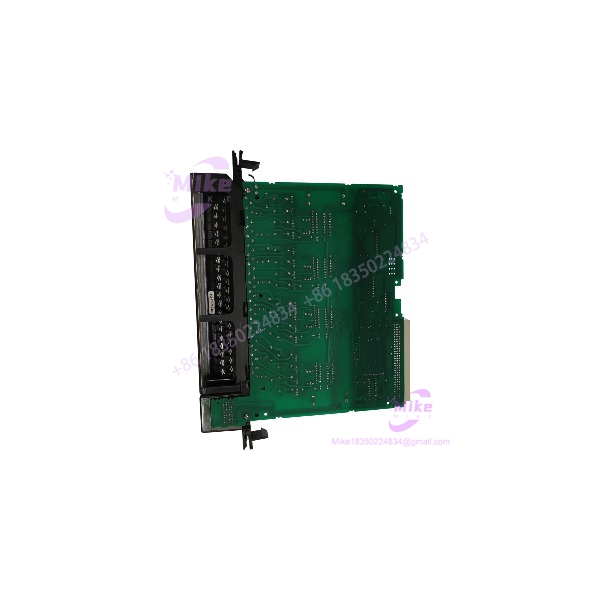
Description
GE Fanuc IC697MDL740 | Series 90-70 DC Output Module
Product Introduction
High-current DC loads can put a different demand on a PLC output card than indicator lamps or low-current interface signals. The GE Fanuc IC697MDL740 is a Series 90-70 positive-logic output module designed for 24/48 VDC applications, with 16 output points arranged in four isolated groups.
Each point supports up to 2 A, subject to the 4 A maximum per group. The module’s high inrush capacity and group-level fusing make it suitable for compatible DC loads such as solenoids, contactors, and indicators. When sourcing an IC697MDL740 for a legacy system, verify the field voltage, group loading, and terminal-board arrangement before treating it as a direct replacement.
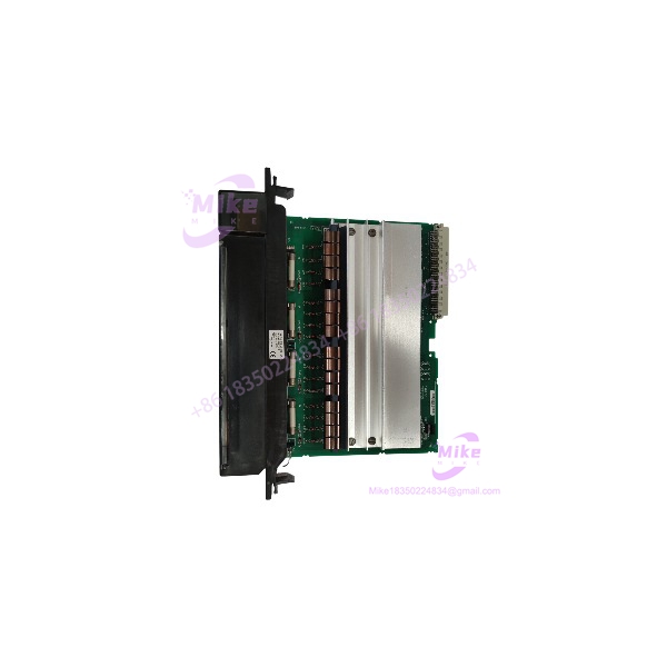
IC697MDL740
Key Technical Specifications
- Catalog Number: IC697MDL740
- Product Family: GE Fanuc Series 90-70
- Module Description: 24/48 VDC, 2 A, 16-point output module
- Output Type: Discrete DC, positive logic
- Number of Outputs: 16
- Output Grouping: Four isolated groups of four points
- Rated Voltage: 24/48 VDC
- Output Voltage Range: 20–60 VDC
- Maximum Output Current: 2 A per point
- Maximum Group Current: 4 A
- Inrush Current: 20 A maximum for 20 ms
- Output Voltage Drop: 0.8 V maximum (0.4 Ω)
- Output Response Time: 2 ms maximum, ON and OFF
- Output Leakage Current: 1 mA maximum
- Group Protection: 10 A fuse per group
- Logic-to-Field Isolation: 1,500 VAC
- Group-to-Group Isolation: 500 VAC
- Backplane Current Requirement: 150 mA from the 5 VDC bus
- Configuration: I/O references are software-configurable; no module DIP switches or jumpers required
- System Interface: Series 90-70 PLC backplane
- Typical Loads: Compatible DC solenoids, contactors, motor starters, and indicator devices
Specifications are drawn from GE Fanuc Series 90-70 product documentation and technical references. Confirm detailed load derating and wiring requirements against the applicable IC697MDL740 datasheet before installation.
Global Sourcing & Live-Test SOP
A discrete output module may power up normally while one or more output points are damaged. For the IC697MDL740, procurement verification should include channel switching and inspection of the group-protection circuitry.
Incoming Verification
- Confirm the catalog number and revision suffix.
- Inspect the housing, backplane connector, terminal-board interface, and visible components.
- Check for corrosion, heat discoloration, damaged contacts, or evidence of field-side overload.
- Confirm whether the field-wiring terminal board is included or sold separately.
Authenticity & Traceability
- Photograph the OEM label, catalog number, and revision markings.
- Record serial/date-code information where available.
- Compare identification details with available GE Fanuc documentation.
- Clearly classify the unit as new surplus, used, or refurbished.
Functional & Output Testing
- Install the module in a compatible Series 90-70 test rack.
- Verify startup behavior and module status.
- Use an appropriate DC field supply within the specified operating range.
- Command individual output points and verify switching with suitable test loads or instrumentation.
- Test representative points in all four output groups.
- Record field voltage, load conditions, and observed output behavior.
- Inspect or verify fuse continuity using an appropriate safe test procedure.
- Do not intentionally overload outputs unless the test procedure and equipment are designed for that purpose.
Extended Run & Test Record
- Perform an extended powered run when test facilities permit.
- Record actual test duration, supply voltage, load conditions, and results.
- Document any channels or protection functions not tested.
- Do not claim a 24-hour heat run unless it was completed and recorded.
ESD-Safe Packaging
- Use ESD-protective packaging and suitable cushioning.
- Protect the backplane connector and terminal interface from impact and contamination.
- Secure the module against movement during transit.
Field Engineer’s Pitfall Guide
- ❗ Respect the 4 A group limit. Although each point is rated for up to 2 A, the combined load on a four-point group must not exceed 4 A. Check simultaneous load demand rather than evaluating each output in isolation.
- ❗ Positive logic means sourcing output. The switches positive DC voltage to the load. Confirm field polarity and load-return wiring against the Series 90-70 wiring diagram; it is not interchangeable with a sinking-output card.
- ❗ Check the voltage range and inrush profile. The module is specified for 20–60 VDC output operation. Loads with high startup current or inductive kickback require particular attention to the manufacturer’s limits and appropriate suppression. The 20 A inrush rating is a specified transient capability, not a continuous operating current.
Intent-Driven FAQ
Q1: What is the GE Fanuc used for?
It is a 16-point positive-logic DC output module for Series 90-70 PLC systems. It switches compatible 24/48 VDC field loads.
Q2: What is the maximum current per output?
Each point is rated for up to 2 A, with a 4 A maximum per four-point group. Both limits must be observed.
Q3: Is the a sourcing or sinking module?
It is a positive-logic sourcing output module. Verify the field wiring and load-return arrangement before connecting it to the application.
Q4: Are the output groups isolated?
Yes. The 16 outputs are arranged in four isolated groups of four points. Group isolation does not eliminate the need to follow the specified field wiring and grounding practices.
Q5: Does the require DIP-switch configuration?
No. I/O references are software-configurable; the module does not require DIP switches or jumpers for that purpose.
Q6: Can the be hot-swapped?
Do not assume live removal or insertion is permitted in your specific Series 90-70 configuration. Follow the applicable hardware manual and site lockout procedures before replacing the module.
Q7: What should I verify before ordering a replacement?
Confirm the catalog number and revision, 24/48 VDC field voltage, sourcing logic, per-point and per-group load, terminal-board compatibility, condition classification, test coverage, and written warranty terms.





