

Description
Foxboro K0143AAAN | Industrial Processor PCB Assembly
Product Introduction
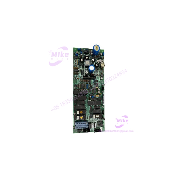
A board-level replacement can be a practical way to keep legacy Foxboro control equipment in service—but only when the replacement matches the original assembly. The Foxboro K0143AAAN is identified in surplus inventory references as a processor PCB assembly, with the board reference ASM 03-187742U01 Rev. B.
This is a configuration-sensitive electronic assembly, not a generic digital I/O module. Public supplier descriptions are inconsistent about its function, and the available evidence does not establish a complete OEM specification sheet. Buyers should verify the printed board number, revision, connectors, and host-system association before treating the K0143AAAN as a direct replacement. Do not rely on generic catalog descriptions or unrelated Foxboro processor specifications to establish compatibility.
K0143AAAN
Key Technical Specifications
- Part Number: K0143AAAN
- Manufacturer: Foxboro
- Assembly Reference: ASM 03-187742U01
- Reported PCB Revision: Rev. B
- Component Type: Processor PCB assembly
- Application: Foxboro industrial control equipment; exact host-system role not fully verified
- Processor Type: Not independently verified
- Memory Capacity: Not independently verified for this exact assembly
- Supply Voltage: Not verified
- Power Consumption: Not verified
- Communication Interfaces: Not verified
- Connector Pinout: Not verified
- Mounting / Backplane Requirements: Confirm against the original assembly
- Operating Temperature: Not verified
- Dimensions / Weight: Confirm from the physical unit
- Firmware Requirements: Verify against the installed system and original board configuration
Specification note: Some reseller content associates K0143AAAN with CP270 controller specifications, while other listings describe it as a redundant output module. These descriptions are not sufficient to establish the exact electrical or functional specification of the K0143AAAN PCB. Do not transfer CP270 processor, memory, network, or power figures to this board without an OEM document explicitly linking those specifications to the exact assembly.
Global Sourcing & Live-Test SOP
For a used or surplus Foxboro , prioritize board identity, revision matching, and controlled functional verification.
1. Incoming Verification
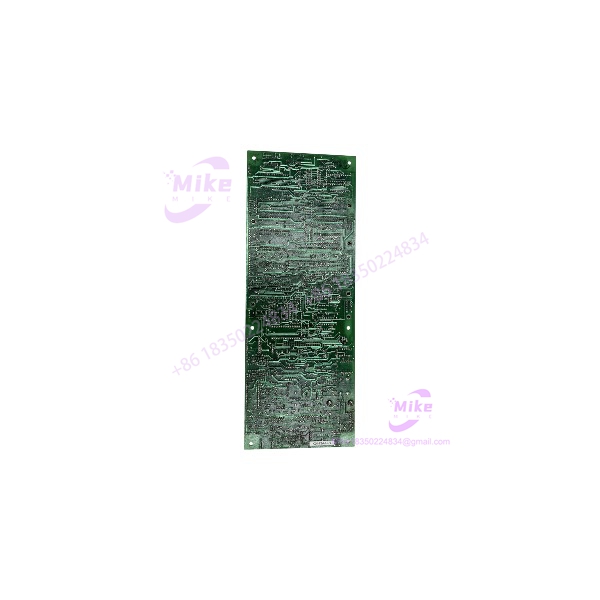
- Photograph the complete PCB, front and back.
- Confirm the marking.
- Check for the assembly reference ASM 03-187742U01 and reported Rev. B marking.
- Record all additional part numbers, serial numbers, and revision labels.
- Inspect connectors, component leads, solder joints, and mounting points.
- Check for corrosion, contamination, heat damage, cracked components, and prior repair work.
- Compare the board layout and connector positions with the original installed unit.
- Document any missing components, modifications, or visible discrepancies.
2. Electrical and Hardware Inspection
- Verify supply requirements from the applicable Foxboro documentation before energizing.
- Do not infer voltage or pinout from a similar Foxboro board.
- Inspect connector contacts and mating interfaces for damage.
- Check for damaged traces, lifted pads, or signs of overheating.
- Use ESD-safe handling and storage procedures.
- Confirm whether the board requires a specific carrier, rack, or backplane.
3. Functional Simulation
A visual inspection alone cannot establish processor-board functionality.
- Use a compatible Foxboro host system or approved test fixture.
- Confirm that the host recognizes the board.
- Check startup diagnostics and any board-specific fault indicators.
- Verify communication with the host system where applicable.
- Test the intended board function using the approved procedure.
- Record diagnostic codes, communication errors, and any intermittent behavior.
- Do not declare the board fully functional based only on power-up or visual condition.
4. Extended Run and Stability Check
Where compatible test equipment is available, conduct an extended operational test.
Monitor:
- Host-system recognition
- Startup consistency
- Diagnostic status
- Communication stability
- Unexpected resets
- Abnormal heating
- Intermittent faults during operation
Record the test duration, host-system model, board revision, test setup, and observed results. Do not claim a 24-hour heat run unless that test was actually completed and documented.
5. Final Preparation and Shipment
- Record the complete model and assembly reference.
- Photograph all labels and connectors.
- Document the actual inspection and test status.
- Preserve customer-specific labels and configuration information.
- Use ESD-safe packaging with mechanical protection.
- Protect connectors from impact and contamination.
- Clearly disclose missing components, known defects, or test limitations.
- State warranty terms only if explicitly offered for the specific unit.
Field Engineer’s Pitfall Guide
❗ Do not misclassify as a digital I/O module
Supplier descriptions conflict, but inventory references identify the as a processor PCB assembly. Confirm the exact board markings and OEM documentation before assigning an I/O function or using it as a substitute for another module.
❗ Do not transfer CP270 specifications without exact documentation
Processor speed, memory, network architecture, and power figures reported for a CP270 controller are not automatically specifications for the PCB. Verify the relationship between the exact board assembly and the host controller before making performance or electrical claims.
❗ Revision and host-system compatibility must be confirmed
A matching part number is not enough if the original assembly has a different revision, connector arrangement, or system configuration. Compare the original PCB and the proposed replacement before installation.
Intent-Driven FAQ
What is the Foxboro ?
The Foxboro is identified in surplus inventory references as a processor PCB assembly, associated with board reference ASM 03-187742U01 Rev. B.
Is the a digital output module?
The available supplier descriptions are inconsistent. Board-level inventory references identify it as a processor PCB assembly, so it should not be marketed or substituted as a digital output module without exact OEM documentation confirming that function.
Is the associated with the Foxboro CP270?
Some supplier content discusses CP270 controller specifications alongside the , but the exact relationship is not sufficiently verified to transfer those specifications to this board. Confirm the association through Foxboro documentation or the original system BOM.
What are the electrical specifications of the ?
A reliable, model-specific supply voltage, power consumption, or connector pinout was not established. Use the original board documentation and nameplate information before energizing the assembly.
Can I replace another Foxboro processor board with ?
Not without verifying the complete part number, board revision, host-system model, connector layout, and firmware/configuration requirements. Processor boards are not interchangeable based on brand or general function alone.
Is the Foxboro obsolete?
The part appears primarily in legacy and surplus inventory channels. A definitive OEM lifecycle statement was not verified. Check with Foxboro/Schneider Electric or a qualified service provider for current support and replacement guidance.
What should I verify before buying a ?
Confirm the exact marking, ASM 03-187742U01 assembly reference, revision, physical condition, host-system compatibility, and seller’s test status. Request clear photos and documented functional-test results when the board is intended for critical equipment.
Bottom Line for Buyers
The is best treated as a legacy processor PCB assembly, reported with board reference ASM 03-187742U01 Rev. B. Conflicting supplier descriptions make it important to avoid unsupported I/O, power, or controller-performance claims.
For procurement, match the physical board and revision against the installed original, verify the host-system association, and request documented condition and test evidence. Do not approve the part as a direct replacement based on a generic Foxboro listing alone.





