


Description
Foxboro FBM241C | 8DI 8DO Compact Discrete I/O Module
Product Introduction
A discrete I/O module can look simple on a procurement sheet—until the field voltage, contact-wetting method, output protection, and termination assembly are wrong. Foxboro FBM241c is a Compact 200 Series module designed specifically for this kind of mixed discrete-control duty: eight contact-sense inputs plus eight externally sourced discrete outputs.
The FBM241c is not interchangeable with every member of the FBM241 family. The suffix matters. The standard Compact FBM241 supports broader voltage-monitor configurations, while FBM241c uses contact-sense inputs and externally sourced outputs. Schneider also defines FBM241d separately, with an internally sourced 12 VDC output arrangement.
For control systems using redundant I/O, FBM241c can operate as a single module or as one half of a redundant pair. In redundant operation, a COUTR function block sends identical output writes to both modules, and the healthy module continues driving the field output if the other module is detected as failed.
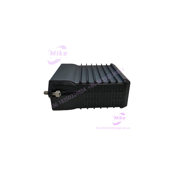
FBM241C
Key Technical Specifications
- Input channels: 8
- Output channels: 8
- Input type: Contact sensing
- Contact-wetting voltage: 24 VDC ±15%
- Nominal contact short-circuit current: 2.5 mA
- Maximum ON-state resistance: 1 kΩ
- Minimum OFF-state resistance: 100 kΩ
- Output type: Externally sourced discrete switch
- Output voltage: 15–60 VDC
- Maximum output load current: 2.0 A per channel
- Maximum OFF-state leakage: 0.1 mA
- Input/output isolation: Galvanically isolated channel-to-channel and channel-to-ground
- Filter/debounce: None, 4, 8, 16, or 32 ms
- Fieldbus: Redundant 2 Mbps HDLC module Fieldbus
- Supply: 24 VDC, +5% / -10%
- Maximum module consumption: 5 W
- Maximum heat dissipation: 6 W
- Operating temperature: -20 to +60°C (-4 to +140°F)
- Storage temperature: -40 to +70°C (-40 to +158°F)
- Relative humidity: 5–95%, noncondensing
- Environmental class: ISA S71.04 Class G3
- Approximate module weight: 185 g
- Module dimensions: 130 × 25 × 150 mm including baseplate connectors
- Current module part number: RH101DJ
- Redundant adapter: RH927BM
Schneider specifies a 600 VAC one-minute withstand between a channel and ground or between channels. That is an isolation test rating—not a permissible continuous operating voltage. The published safety warning specifically states that the channels are not intended for permanent connection to hazardous-voltage circuits.
FBM241C Input Architecture
The input side of FBM241c is designed for discrete contact sensing rather than a conventional analog signal.
Each channel detects an open or closed contact. The module provides approximately 24 VDC ±15% for contact wetting, with a nominal short-circuit current of 2.5 mA. Schneider specifies a maximum 1 kΩ resistance for the ON state and a minimum 100 kΩ resistance for the OFF state.
This matters when replacing older discrete input hardware. A field device that technically behaves like a switch may still be unsuitable if its leakage current, series resistance, or interface electronics do not meet the FBM241c contact-sense characteristics.
FBM241C Output Architecture
The eight outputs are externally sourced discrete switches.
Each channel supports up to 60 VDC and 2 A maximum, with a maximum OFF-state leakage current of 0.1 mA. The termination assembly determines how the external field power, protection, fusing, or relay interface is implemented.
For an inductive load, Schneider notes that an appropriate protective diode or metal-oxide varistor may be required across the load. Do not assume the FBM itself provides every form of field-load suppression required by the installation.
Termination Assembly Selection
This is where many replacement orders go wrong.
For Compact FBM241c, Schneider documents several termination configurations, including:
- RH916JW — 8 contact-sense inputs with 24 VDC wetting; 8 externally sourced outputs, 15–60 VDC at 2 A maximum, protected/fused.
- RH916UD — 8 contact-sense inputs; 8 externally sourced outputs below 60 VDC at 2 A maximum, unprotected/no fuse.
- RH916AW — relay-based output termination, SPDT/Form C, below 30 VDC at 5 A or up to 250 VAC at 5 A; total current across all eight relays is limited to 12 A simultaneously.
- RH916QQ — relay-based output termination with group isolation.
Therefore, purchasing RH101DJ alone does not necessarily define the complete field interface. The installed TA must be checked against the voltage, load current, protection requirement, and isolation architecture.
The Compact module connects to its TA through a Type 4 or Type 4H termination cable, with cable lengths available up to 30 m (98 ft). The baseplate and TA use 37-pin D-subminiature connections.
Redundancy and Maintenance
FBM241c supports single or redundant operation.
For redundancy, two modules are installed in adjacent odd/even baseplate positions. The redundant adapter connects the two baseplate termination interfaces to one termination cable and common TA. The RH927BM redundant adapter is the current specified adapter for the Compact FBM241/241c/241d family.
The COUTR function block manages redundant output writes and initialization. Both modules receive identical output commands, so the standby side is continuously exercised rather than sitting completely dormant.
If one module is detected as failed, its corresponding output is marked BAD and the healthy module continues driving the discrete output. Either redundant module can be removed and replaced without disconnecting field termination, power, or communication cabling.
Fieldbus and Logic Functions
The Compact FBM241c communicates with its associated Fieldbus Communications Module or Control Processor through the redundant 2 Mbps HDLC module Fieldbus.
Either Fieldbus path A or B can be used. If one path becomes unsuccessful or the system switches communication paths, the module continues communication through the active path.
At the application level, the module supports:
- Discrete I/O processing
- Ladder Logic
- Configurable input filtering
- Fail-safe configuration
- Fail-safe fallback
- Sustained outputs
- Momentary outputs
- Configurable pulse-output interval for momentary-output operation
This makes the FBM241c more than a passive signal concentrator. Its onboard processor performs application and diagnostic functions associated with the discrete I/O subsystem.
Global Sourcing & Live-Test SOP
For a used, surplus, or refurbished FBM241C, treat the module and termination assembly as separate procurement objects.
1. Inbound Verification
- Confirm the module marking as FBM241c.
- Verify the hardware part number against RH101DJ.
- Photograph the serial number and revision markings.
- Inspect the Compact housing for cracking, deformation, contamination, or heat damage.
- Check the baseplate connectors and module mounting screws.
- Verify the proposed TA and redundant adapter separately.
- Preserve OEM traceability and available factory documentation.





