


Description
Foxboro FBM230 | 4-Port Serial Field Device Integrator
Product Introduction
The Foxboro FBM230 is built for a different problem than a conventional FBM analog or discrete card. Instead of terminating process transmitters directly, it provides a serial communications bridge between single-ported field devices and the Foxboro control system.
Each of the four FBM230 ports can be independently configured for RS-232, RS-422, or RS-485. That allows one module to interface with different device types or communication arrangements without forcing every port into the same electrical standard. Schneider’s documentation identifies the FBM230 as the Field Device System Integrator Module, Four Serial Ports, Single.
The module uses downloadable software drivers to interpret device-specific protocols and convert field-device data into Foxboro Distributed Control Interface (DCI) data. This is why the FBM230 should be evaluated as a protocol-integration component, not simply as a four-channel serial converter.
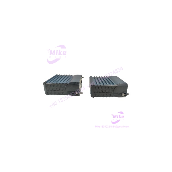
FBM230
Key Technical Specifications
- Model: FBM230
- Function: Field Device System Integrator Module
- Number of Serial Ports: 4
- Port Configuration: Independently selectable
- Electrical Interfaces: RS-232, RS-422, RS-485
- RS-485 Capacity: Up to 64 devices total
- RS-485 Arrangement: Up to 16 devices per port
- Direct RS-232/RS-422 Capacity: Up to 4 devices
- Maximum DCI Connections: 2,000
- Fastest Allowed ECB Block Period: 500ms
- Supported Data: 2-byte/4-byte signed or unsigned integers, 4-byte IEEE single-precision floating point, and binary values
- Transmission Rates: 300, 600, 1200, 2400, 4800, 9600, 19200, 38400, 57600, and 115200 baud
- Character Format: 8-bit characters
- Parity: Odd, even, or none
- Stop Bits: 1 or 2
- Module Fieldbus: Redundant 2Mbps
- Supply: 24VDC +5%/-10%
- Maximum Consumption: 7W
- Maximum Heat Dissipation: 7W
- Operating Temperature: -20°C to +70°C
- Storage Temperature: -40°C to +70°C
- Relative Humidity: 5–95%, noncondensing
- Environmental Rating: ISA S71.04 Class G3
- Module Weight: Approximately 284g
- Module Dimensions: 102 × 45 × 104mm; 114mm including mounting lugs
- Module Part Number: P0926GU
- Ring-Lug TA: P0926PA
- Compression-Screw TA: RH926GH, superseding P0926GH
Serial Communication Architecture
The ‘s four ports are independently configurable. In practical terms, Port 1 can be RS-485 while another port is configured for RS-232 or RS-422, depending on the field-device architecture.
Supported physical interfaces include:
- RS-232: Direct point-to-point communication
- RS-422: Four-wire serial communication
- RS-485: Multidrop communication
For RS-485, the specification permits up to 16 devices per port, with a maximum of 64 devices across the four ports. For direct RS-232 or RS-422 connections, up to four devices can be connected.
The supported baud rates extend from 300 baud through 115.2kbaud, with configurable parity and stop-bit settings. These parameters are not merely documentation details; an incorrect baud rate, parity setting, termination resistor, or device address can make a perfectly healthy appear to be defective.
Protocol Driver and DCI Integration
The uses downloadable I/O software drivers.
The hardware itself is generic. The loaded driver determines how the module interprets the particular field-device protocol, while the configurator handles parameters such as communication standard, baud rate, parity, device address, scan rate, and the amount of data transferred per transaction.
This architecture allows the Foxboro control system to access data from external instruments and controllers through standard DCI blocks.
Supported DCI data types include:
- Binary input/output
- Integer input/output
- Real input/output
- Packed digital input/output
- Pulse output
- String input/output
- Redundant binary or real input functions
With the specified maximum of 2,000 DCI connections, the can represent large quantities of external-device data in the Foxboro control database. The theoretical data capacity can reach up to 2,000 analog values or as many as 64,000 digital values when packed into appropriate DCI connections, subject to the installed driver and actual device configuration.
RS-485 Installation Considerations
RS-485 is where field commissioning discipline matters.
The termination assembly provides switch-selectable termination resistors for RS-422 and RS-485 communications. The TA also provides the physical connection between the and the field devices.
A typical RS-485 installation should therefore be checked for:
- Correct device address
- Correct baud rate
- Matching parity
- Correct stop-bit configuration
- Proper bus polarity
- Correct cable topology
- Appropriate termination
- Shielding and grounding
- Duplicate device addresses
- Maximum cable length
- Device-specific protocol-driver compatibility
The specified RS-422/RS-485 field connection can extend to approximately 1,200m (3,937ft) under the documented conditions. RS-232 is much more restrictive; the specification gives up to 15m (50ft) for custom RS-232 cables following the applicable EIA requirements.
Termination Assembly Identification
Do not treat the TA as an interchangeable generic serial terminal block.
The has dedicated termination assemblies for its four communication ports. The documented versions include:
- P0926PA: Ring-lug termination assembly
- RH926GH: Compression-screw termination assembly, superseding P0926GH
The TA provides four DB-25 connectors for RS-232 connections and three-tier termination for RS-422/RS-485 wiring. Its DIP-switch functions also provide RS-232 signal routing and selectable RS-422/RS-485 termination.
The termination cable is Type 5, with documented LSZH cable lengths of 1m, 2m, 3m, and 5m.
For procurement, verify the complete assembly:
module + correct TA + correct termination cable + appropriate driver/configuration.
A module alone does not constitute a complete serial integration interface.
Fieldbus Communication
The communicates with the Foxboro control architecture through the redundant 2Mbps Module Fieldbus.
Compatible processor/interface equipment documented for the module includes:
- FCM100E
- FCM100Et
- FCP270
- FCP280
The accepts communication from either redundant Fieldbus path. If one path fails or is switched at the system level, communication can continue over the active path.
This redundancy is at the module Fieldbus level. It should not be confused with the FBM231, which is the redundant version of the Field Device System Integrator module. Schneider’s current documentation separately identifies as the single version and FBM231 as the redundant version.
Global Sourcing & Live-Test SOP
For a used or surplus , a basic power-on test is not enough. The critical question is whether the serial ports actually communicate with a compatible device using the required driver and configuration.
1. Inbound Verification
- Photograph the complete module label.
- Verify the identification.
- Record the module serial number.
- Confirm the hardware part number.
- Inspect the Fieldbus connector.
- Inspect the four-port communication interface.
- Check for bent contacts, oxidation, contamination, or enclosure damage.
- Verify the supplied TA part number separately.
- Confirm whether the unit includes the termination cable.





