Description
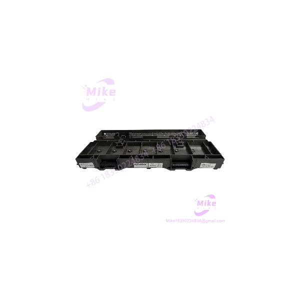
Emerson KJ4001X1-BE1 | DeltaV 8-Wide I/O Carrier
Product Introduction
A failed I/O carrier can take more than one channel offline, particularly when the fault affects the shared LocalBus or field-power distribution. Replacing the carrier requires more than matching its width: the DeltaV hardware generation, power distribution, shield arrangement, and installed module configuration all need to line up.
The Emerson KJ4001X1-BE1 is an 8-wide DeltaV I/O carrier supplied with a shield bar. Emerson’s legacy ATEX instruction sheet specifies a 12.6 VDC LocalBus circuit rated at 8 A and a 30 VDC field-circuit rating of 6.5 A. The carrier serves as supporting system hardware; it does not perform the signal processing of the I/O modules installed on it.
For a maintenance team sourcing this part, the main objective is to restore the original carrier arrangement without introducing a power-distribution or compatibility mismatch. Verify the full model number, shield bar, carrier condition, associated modules, and actual field-power design before installation.
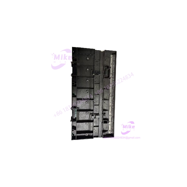
KJ4001X1-BE1
Key Technical Specifications
- Manufacturer: Emerson
- Model: KJ4001X1-BE1
- Platform: DeltaV M-Series I/O
- Component Type: 8-wide I/O carrier
- Shielding: Shield bar included in the specified carrier configuration
- LocalBus Circuit: 12.6 VDC at 8 A
- Field Circuit Power: 30 VDC at 6.5 A
- Ambient Temperature: −40°C to +70°C
- Shock Resistance: 10 g, half-sine wave, 11 ms
- Vibration Resistance: 1 mm peak-to-peak from 5–16 Hz; 0.5 g from 16–150 Hz, per the legacy instruction sheet
- Relative Humidity: 5–95%, non-condensing
- Ingress Protection: IP20
- Airborne Contaminants: ISA-S71.04-1985, Class G3
- Maintenance: No user-serviceable parts; calibration not required
- Installation Reference: Emerson ATEX Instruction Sheet D803013X012
Ordering-number qualification: Suppliers associate the KJ4001X1-BE1 with several 12P0818X0xx ordering numbers, including X032, X042, X062, X072, and X082. These should be treated as supplier cross-references, not assumed interchangeable revisions. Verify the exact number on the carrier label and the applicable DeltaV documentation before purchasing.
Global Sourcing & Live-Test SOP
For a used or surplus KJ4001X1-BE1, the inspection should focus on mechanical integrity, LocalBus contacts, field-power distribution, and shield-bar condition. A carrier that looks intact may still have damaged contacts or intermittent connections.
1. Inbound Verification
- Photograph the complete product label and all visible part numbers.
- Confirm the exact model: KJ4001X1-BE1.
- Record the serial number, revision, and manufacturing information where available.
- Inspect the carrier body, mounting points, connectors, and shield bar.
- Check for bent contacts, corrosion, cracked plastic, heat discoloration, or evidence of previous repair.
- Verify that the shield bar and required mounting hardware are present.
- Compare the supplier’s ordering-number cross-reference with the physical label.
- Retain available OEM paperwork and supplier traceability documents.
2. Mechanical and Electrical Inspection
- Inspect the LocalBus interface for damage or contamination.
- Check field-power connections and terminal interfaces for looseness or heat damage.
- Confirm that the carrier fits the intended DeltaV M-Series installation.
- Verify the carrier width and shield-bar arrangement against the original assembly.
- Check the system’s LocalBus and bussed field-power requirements against the carrier ratings.
- Do not assume that a carrier with the same width has the same electrical configuration.
3. Controlled System Verification
A carrier is not a standalone I/O processing device, so meaningful functional validation requires a compatible DeltaV test arrangement.
- Confirm the carrier is installed in the correct system configuration.
- Verify LocalBus and field-power wiring before energizing.
- Confirm the installed I/O modules and terminal blocks are correctly seated.
- Check for system diagnostics associated with the carrier or installed modules.
- Verify module communication and I/O operation using the appropriate DeltaV diagnostic tools.
- Record faults, unexpected behavior, or configuration discrepancies.
4. Extended Run and Documentation
Where a compatible test setup is available, conduct an extended operating test with representative installed modules and power distribution.
Monitor:
- LocalBus stability
- Field-power behavior
- Module communication
- Intermittent connection faults
- Abnormal heating or discoloration
- System diagnostics and unexpected resets
Record the test duration, carrier label/revision, installed module configuration, power arrangement, and observed results. A visual inspection alone should not be described as a full functional test.
5. Final Preparation and Shipment
- Photograph the carrier and shield bar before packaging.
- Record the exact model, revision, and supplier cross-reference.
- Protect exposed connectors and contacts against impact and contamination.
- Use ESD-safe packaging when handling the carrier with electronic assemblies.
- Identify whether the shield bar and mounting accessories are included.
- State the actual condition and test status.
- Do not claim factory-sealed condition or a specific warranty without supporting evidence.
Field Engineer’s Pitfall Guide
❗ Do not remove or install the carrier with system power energized
The legacy Emerson instruction sheet states that the carrier cannot be removed or inserted with system power energized. It also requires field power to be removed before connecting or removing the device, and power to be de-energized before disconnecting carriers or LocalBus Extender cables. Follow the applicable OEM and plant isolation procedures.
❗ Keep bussed field power within the documented limit
Emerson’s instruction sheet states that bussed field power must not be connected to a supply capable of generating or containing a potential above 30 VDC. Verify the actual supply and field-power distribution design; do not treat the carrier’s 30 VDC rating as permission to use a higher-voltage source.
❗ Do not confuse the carrier with the module cover
The is the 8-wide I/O carrier with shield bar. KJ4001X1-FA1 is identified in the carrier instructions as a module cover for permanently unoccupied locations. They are different components and should not be listed or ordered as equivalents.
Intent-Driven FAQ
What is the Emerson ?
The is an Emerson DeltaV 8-wide I/O carrier with shield bar. It provides the supporting carrier interface for compatible DeltaV I/O hardware.
Is the an I/O module?
No. It is a carrier, not a signal-processing I/O module or controller. The required I/O modules and associated terminal blocks must be selected separately according to the installed system configuration.
What are the LocalBus and field-power ratings?
The legacy Emerson instruction sheet specifies 12.6 VDC at 8 A for the LocalBus circuit and 30 VDC at 6.5 A for field-circuit power. Confirm the applicable documentation and system design before installation.
Can the be hot-swapped?
Do not assume so. Emerson’s instruction sheet prohibits removal or insertion with system power energized and specifies additional field-power isolation requirements. Follow the OEM instructions for the actual installation.
Is the obsolete?
It is a legacy DeltaV carrier, and suppliers identify it as discontinued by the manufacturer. Availability and condition therefore depend on remaining surplus stock, repair inventory, and supplier verification.
Are all 12P0818X0xx numbers interchangeable with ?
Do not assume they are. Supplier listings associate multiple 12P0818X0xx numbers with the BE1 carrier, but cross-references can vary. Confirm the complete label and applicable hardware revision before accepting an alternate number.
What should be checked before buying a replacement ?
Confirm the exact model, label and revision, shield-bar condition, LocalBus and field-power requirements, carrier compatibility, and supplier test evidence. For a production system, compare the candidate carrier against the installed DeltaV drawings and OEM documentation before commissioning.
Bottom Line for Buyers
The is a legacy DeltaV 8-wide I/O carrier with shield bar, documented for a 12.6 VDC, 8 A LocalBus circuit and a 30 VDC, 6.5 A field circuit.
For replacement procurement, prioritize exact model and label verification, mechanical condition, shield-bar completeness, and compatibility with the installed DeltaV carrier arrangement. Confirm the applicable OEM installation requirements before returning the system to service.