

Description
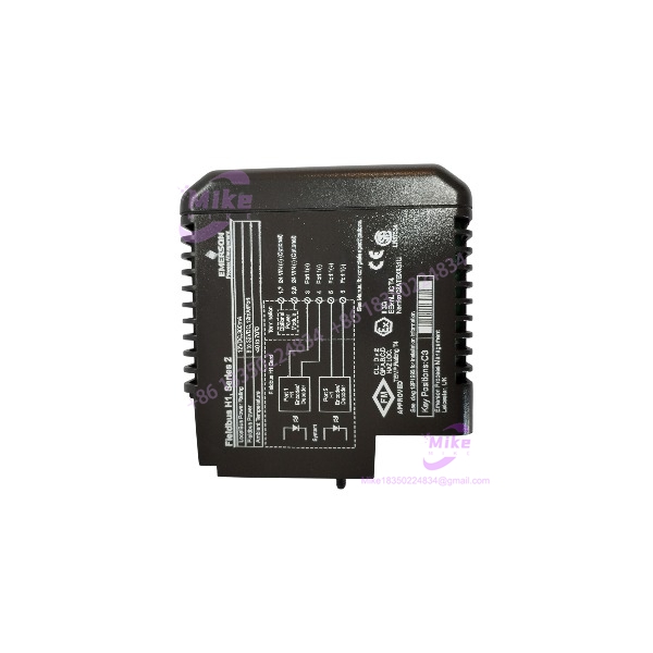
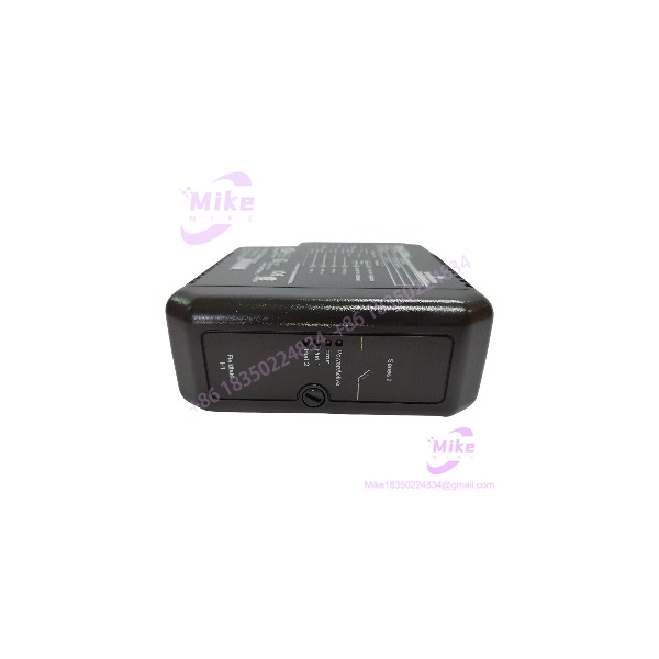
Emerson KJ3242X1-BA1 | DeltaV Series 2 Fieldbus H1 Card
Product Introduction
FOUNDATION Fieldbus H1 installations depend on the correct interface hardware, fieldbus power arrangement, and segment wiring. A replacement card must match the existing DeltaV architecture—not merely the general Fieldbus H1 description.
The Emerson KJ3242X1-BA1 is a Series 2 FOUNDATION Fieldbus H1 card for the DeltaV M-series I/O subsystem. Emerson documents a 12 VDC at 300 mA LocalBus requirement, fieldbus power of 9–32 VDC at 12 mA per port, and D6 terminal-block keying. The card is intended for legacy DeltaV applications; Emerson’s M-series Fieldbus documentation identifies KJ3242X1-BA1 or BA2 for systems requiring earlier-generation H1 interface cards.
For maintenance and procurement teams, the KJ3242X1-BA1 is a configuration-sensitive communications spare. Verify the installed terminal block, keying, fieldbus segment requirements, and DeltaV version before commissioning a replacement.
KJ3242X1-BA1
Key Technical Specifications
- Model Number: KJ3242X1-BA1
- Manufacturer: Emerson Automation Solutions
- Platform: DeltaV M-series
- Card Generation: Series 2
- Module Type: FOUNDATION Fieldbus H1 interface card
- LocalBus Power: 12 VDC at 300 mA
- Fieldbus Power: 9–32 VDC at 12 mA per port
- Terminal-Block Key Position: D6
- Ambient Operating Temperature: −40°C to +70°C
- Shock Rating: 10 g half-sine wave for 11 ms
- Vibration: 1 mm peak-to-peak from 2–13.2 Hz; 0.7 g from 13.2–150 Hz
- Relative Humidity: 5–95%, noncondensing
- Airborne Contaminants: ISA-S71.04-1985 Class G3
- Protection Rating: IP20
- Maintenance: No user-serviceable parts; do not disassemble
- Calibration: Not required, per Emerson instruction sheet
- Removal/Insertion: Subject to OEM power-isolation and hazardous-area restrictions
- Compatibility: Requires the correct DeltaV carrier, terminal block, D6 keying, and approved system configuration
These values are documented in Emerson’s model-specific ATEX instruction sheet. The exact fieldbus segment count and complete application configuration should be verified against the installed hardware and DeltaV documentation rather than inferred from the card model alone.
Global Sourcing & Live-Test SOP
For a used or surplus KJ3242X1-BA1, procurement acceptance should establish exact identity, physical condition, and compatibility with the target DeltaV system.
1. Inbound Verification
- Photograph the complete nameplate and model markings.
- Confirm , including the full suffix.
- Record serial number, hardware revision, and associated ordering number where available.
- Inspect the card edge connector, faceplate, LEDs, and housing for damage.
- Check for corrosion, contamination, heat discoloration, cracked components, or evidence of unauthorized repair.
- Verify D6 terminal-block keying against the approved OEM documentation.
- Retain supplier traceability records and condition disclosures.
2. Configuration & Compatibility Review
- Identify the installed DeltaV M-series carrier and companion terminal block.
- Verify D6 keying and card-to-terminal-block compatibility.
- Confirm the full model number against the removed card.
- Review the installed DeltaV version and applicable Fieldbus H1 interface requirements.
- Verify fieldbus power and segment termination requirements.
- Confirm the intended redundancy arrangement, if applicable.
- Do not assume that BA1 and BA2 are interchangeable without checking the approved replacement path.
3. Bench Inspection & Power-Up
- Use a compatible DeltaV test carrier and approved test procedure.
- Verify the 12 VDC LocalBus supply and current capacity.
- Confirm that fieldbus power is within the documented 9–32 VDC range.
- Inspect connector engagement and card seating.
- Observe startup and diagnostic LED behavior.
- Check for unexpected faults or abnormal heating.
- Do not use improvised pin connections or an unverified adapter to energize the card.
4. Fieldbus Communications Diagnostics
A successful power-up does not establish Fieldbus H1 communications performance. Test the card in a compatible DeltaV configuration.
- Connect a known-good H1 test segment or approved fieldbus simulator.
- Verify segment wiring, power, and termination against the system documentation.
- Confirm communications with known-good field devices.
- Review DeltaV diagnostics for communication faults and device status.
- Where redundancy is used, test the intended configuration using the approved system procedure.
- Record communication errors, intermittent faults, and diagnostic status.
Do not advertise the card as fully fieldbus-tested if the test only confirms power-up or LED activity.
5. Extended Run & Stability Check
Where the test setup permits, perform an extended run with representative Fieldbus H1 traffic.
Monitor:
- Card diagnostic status
- Fieldbus segment stability
- Device communication faults
- Unexpected resets
- Connector seating and mechanical stability
- Abnormal heating
- Redundancy behavior, where applicable and tested
Record the test duration, carrier, terminal block, fieldbus configuration, and results. Do not claim a 24-hour burn-in unless it was actually completed and documented.
6. Final Preparation & Shipment
- Record the exact model, ordering number, revision, and serial number.
- Photograph the card and connector condition before packing.
- Clearly disclose used, refurbished, repaired, or untested condition.
- Include only accessories confirmed as part of the sale.
- Protect the card against ESD, impact, and connector damage.
- Retain test and traceability records with the shipment.
Field Engineer’s Pitfall Guide
❗ D6 keying must match the terminal block
Emerson’s instruction sheet identifies terminal-block key position D6 for the . Confirm the installed terminal block and approved carrier arrangement before installation. Mechanical fit alone does not establish compatibility.
❗ Do not treat energized removal as unrestricted hot swapping
Emerson’s ATEX documentation restricts removal or insertion with system power energized. A limited exception applies only when the area is known to be non-hazardous and only one unit is handled at a time. Non-sparking field circuits must be de-energized before removal or insertion. Follow the OEM procedure and site isolation requirements.
❗ Confirm the fieldbus power and segment design
The documented fieldbus power range is 9–32 VDC at 12 mA per port. Confirm the actual segment power supply, field-device load, termination, and loop assessment requirements. Do not assume the card alone provides all power required by the fieldbus network.
Intent-Driven FAQ
What is the Emerson ?
It is a DeltaV M-series Series 2 FOUNDATION Fieldbus H1 interface card. It provides the H1 interface within a compatible DeltaV control-system configuration.
What is the LocalBus power requirement?
Emerson specifies 12 VDC at 300 mA for LocalBus power. Use the OEM specification and approved carrier configuration when checking power capacity.
What fieldbus power does the card support?
The documented fieldbus power range is 9–32 VDC at 12 mA per port. Verify the segment design and field-device power requirements before installation.
What terminal-block key position does it use?
The uses D6 terminal-block keying. Confirm the installed terminal block and carrier arrangement before replacement.
Is the suitable for redundant DeltaV Fieldbus H1 applications?
Emerson’s M-series documentation identifies a redundant H1 interface-card-and-terminal-block arrangement using two interface cards and a redundant terminal block. Confirm the complete hardware configuration and approved card pairing before treating a single BA1 card as a complete redundant assembly.
Is the hot-swappable?
Do not assume unrestricted hot swapping. Emerson’s ATEX instruction sheet restricts energized removal/insertion, with a limited exception for a known non-hazardous area when only one unit is handled at a time. Non-sparking field circuits must be de-energized before removal or insertion.
What should buyers verify before purchasing a used ?
Confirm the full model and ordering-number markings, serial number, revision, D6 keying, companion terminal block, and DeltaV configuration. Request clear photos and a written description of the seller’s actual test scope. Verify any proposed alternate model against Emerson’s approved replacement documentation.
Bottom Line for Buyers
The is a DeltaV M-series Series 2 FOUNDATION Fieldbus H1 interface card. Emerson documents its 12 VDC at 300 mA LocalBus requirement, 9–32 VDC fieldbus power at 12 mA per port, D6 terminal-block keying, and −40°C to +70°C ambient range.
For procurement, specify the complete model number, request nameplate and connector photographs, and verify D6 terminal-block compatibility and the intended H1 segment configuration. Emerson’s M-series documentation identifies BA1/BA2 for earlier DeltaV versions, so confirm the approved replacement path before substituting another revision.





