

Description
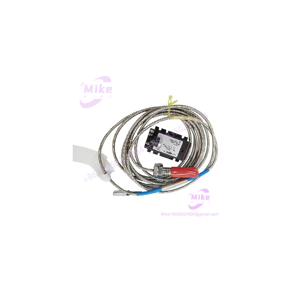
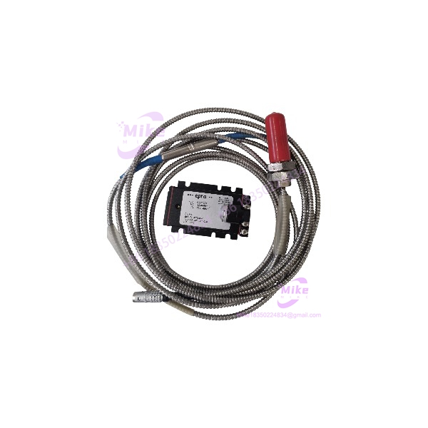
Emerson EPRO PR6424/010-010 | 16 mm Eddy Current Probe
Architect’s Product Breakdown
The Emerson EPRO PR6424/010-010 is a 16 mm eddy current proximity probe used in machinery protection and condition monitoring systems. It measures the distance between the probe tip and a conductive shaft target without mechanical contact. Typical applications include steam turbines, gas turbines, centrifugal compressors, pumps, and large motors where shaft vibration, axial displacement, and eccentricity measurements are required for operational monitoring.
The standard 16 mm PR6424 configuration specifies 4 V/mm nominal sensitivity, a ±2.0 mm static measurement range, and a nominal center air gap of approximately 2.7 mm. The probe is designed for a specified ferromagnetic steel target, commonly 42CrMo4. These values are configuration-dependent and should be confirmed against the OEM datasheet for the exact unit. The PR6424/010-010 can be used with a compatible EPRO signal converter, such as the CON021, but the converter’s calibration must match the probe.
For legacy machinery monitoring systems, the main replacement risks are incorrect calibration, incompatible cable assemblies, and mismatched monitor scaling. Do not approve a replacement based solely on the PR6424 family number or a matching connector. Verify the complete ordering code, mounting thread, cable length, connector type, target material, and receiving monitor input configuration before installation. Where the probe is part of a trip-critical protection channel, validate the complete measurement chain before returning the machine to service.
PR6424/010-010
Key Technical Specifications
| Parameter | Specification |
|---|---|
| Model | PR6424/010-010 |
| Manufacturer | Emerson EPRO |
| Product type | Eddy current displacement probe |
| Sensor family | 16 mm |
| Measurement principle | Non-contact eddy current |
| Nominal sensitivity | 4 V/mm (101.6 mV/mil) |
| Static measurement range | ±2.0 mm |
| Dynamic measurement range | Up to 1,000 µm, subject to system configuration |
| Nominal center air gap | Approximately 2.7 mm |
| Linearity | ≤ ±1.5% |
| Target material | Ferromagnetic steel; 42CrMo4 reference |
| Minimum shaft diameter | 80 mm |
| Mounting thread | M18 × 1.5, verify exact configuration |
| Cable configuration | Armored cable and connector arrangement must be verified |
| Cable length | Confirm the exact supplied assembly; do not assume a standard length |
| Compatible converter | CON021 or another explicitly approved converter configuration |
| Output signal | Converter-dependent analog voltage |
| Probe operating temperature | Verify the applicable probe revision and installation conditions |
| Converter frequency response | CON021 specification: 0–20 kHz at −3 dB |
| Converter operating temperature | CON021 specification: −30°C to +100°C |
Specification note: The PR6424/010-010 is the probe model, not a complete probe-and-converter assembly. Confirm the converter, cable, and calibration requirements separately. Do not apply converter specifications to the probe itself.
Field Engineer’s Pitfall Guide
Warning 1 — Do not confuse probe sensitivity with converter output scaling.
The nominal 4 V/mm sensitivity describes the specified PR6424 measurement configuration. The actual system output depends on the matched converter and its calibration. If a replacement probe has a different sensitivity or range, the monitor may report incorrect shaft movement even though the signal appears stable.
Warning 2 — Check the mounting thread and installation clearance.
The 16 mm PR6424 family uses specific mounting arrangements, including M18 × 1.5 configurations. Confirm the exact mechanical dimensions before removing the existing probe. Establish the installation gap according to the OEM procedure; an incorrect gap can reduce the available measurement range in one direction.
Warning 3 — Verify the complete cable assembly.
Cable length, connector type, shielding, and armored construction must match the approved sensor configuration. An improvised cable extension or incompatible connector can compromise the measurement chain. For trip-critical service, verify the installed probe and converter combination before enabling the protection channel.
QA & Testing SOP
- Visual and origin inspection: Inspect OEM markings, model and serial numbers, probe tip, threaded body, cable jacket, and connector. Record available traceability documentation.
- Electrical inspection: Verify cable continuity where applicable, connector condition, and compatibility with the intended converter.
- Live functional testing: Connect the probe to the approved converter and use a calibrated target fixture to test the measurement response.
- Measurement diagnostics: Verify sensitivity, linearity, signal stability, and output response across the specified measurement range.
- Documentation: Record the complete model number, serial number, converter designation, calibration information, and test results. Firmware recording is generally not applicable to this analog probe.
- Protective packaging: Protect the probe tip, connector, and cable from impact, moisture, crushing, and excessive bending.
Acceptance requirement: A continuity check or power-on test alone does not establish measurement accuracy. Require documented functional testing and confirmation of calibration compatibility before installing the probe in a machinery protection system.
Technical FAQ
Q1. Can I replace another PR6424 probe with the PR6424/010-010?
Not without checking the full ordering code, mechanical dimensions, cable configuration, sensitivity, and measuring range. The shared PR6424 family designation does not guarantee interchangeability.
Q2. Does the PR6424/010-010 require a CON021 converter?
The probe requires a compatible signal converter to form the intended measurement chain. The CON021 is one possible pairing, provided its calibration and electrical configuration match the probe. Confirm the existing system documentation before ordering a replacement.
Q3. Can I hot-swap the probe while the turbine is running?
Do not assume online replacement is permitted. Disconnecting the probe may interrupt a machinery protection channel or trigger an alarm or trip. Follow the plant’s approved isolation, maintenance, and bypass procedures before disturbing the installed channel.
Q4. Will the probe retain its configuration after a power failure?
The PR6424/010-010 is analog sensing hardware, not a programmable controller. Monitoring thresholds, channel scaling, and trip logic reside in the receiving monitoring system. Verify the restored channel configuration and signal after power returns.
Q5. Does new-surplus stock include an OEM warranty?
Not automatically. New-surplus describes a sales condition, not guaranteed manufacturer warranty coverage. Obtain written confirmation of condition, functional test status, warranty provider, warranty period, and return terms before placing the purchase order.





