Description
Emerson 5X00225G01 | Direct Replacement Control Base Assembly
Architect’s Product Breakdown
The Emerson Ovation 5X00225G01 is the structural and electrical backbone for OCR1100-series Ovation Controllers. While I/O modules sit on standard 16-slot I/O bases, the controller drop itself relies on dedicated process control base assemblies like the 5X00225G01 to house the central processing cards (CPU cards, I/O interface cards, and power supply links). It routes high-speed internal CompactPCI bus communications, 24 VDC redundant logic power, and local I/O branch connections across the controller chassis.
Engineered for mission-critical applications in power generation, water treatment, and continuous process plants, this base assembly provides the physical layer required to achieve true “bumpless” automatic failover between primary and secondary redundant controllers. High-integrity traces and multi-layer ground planes protect CPU-to-I/O execution timing against external high-EMI transients typically found in turbine halls or high-voltage switchgear environments.
In plant life-cycle management, replacing a damaged or corroded controller base assembly requires exact hardware revision matching. Bent connector pins, trace delamination from thermal cycling, or degraded power rails on an aging base chassis can manifest as erratic drop dropouts, bus communication timeouts, or random failover triggers. Swapping in a verified 5X00225G01 base restores backplane bus integrity without requiring logic changes or software database re-flashing.
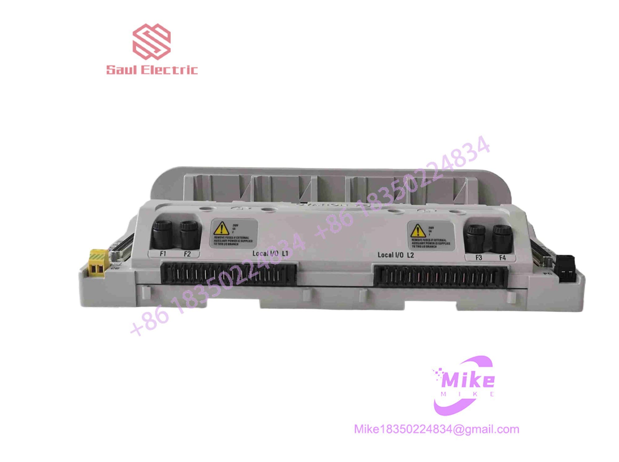
5X00225G01
Key Technical Specifications
| Parameter | Specification / Value |
| Component Type | Controller Chassis Base Assembly |
| System Compatibility | Emerson Ovation OCR1100 Controller Series |
| Bus Architecture | Industrial CompactPCI / Local Ovation Backplane Bus |
| Power Input Distribution | Dual Redundant 24 VDC Inputs (via cabinet power rails) |
| Mounting Configuration | Direct DIN-Rail or Cabinet Panel Mounting |
| Operating Temperature | 0°C to +60°C (32°F to 140°F) |
| Storage Temperature | -40°C to +85°C (-40°F to 185°F) |
| Humidity Range | 5% to 95% non-condensing |
| Vibration / Shock Rating | Industrial Control Grade (IEC 60068-2 standards) |
| Security Certification | Achilles Level 1 compliant (when integrated into OCR drop) |
Field Engineer’s Pitfall Guide
WARNING: Backplane Pin Bending During CPU Insertion
CompactPCI edge connectors on the 5X00225G01 feature high-density pin fields. Never slide controller CPU cards (e.g., 5X00481 series) or IOIC cards into the base at an angle or with excessive force. A single bent or cross-bridged pin on the backplane will halt controller boot sequences, freeze bus communication, or cause catastrophic short circuits across the 24 VDC internal power rails.
WARNING: Dual Power Feed Phase Isolation
I’ve seen a plant trip an entire boiler drop during routine maintenance because both redundant 24 VDC feeds landed on the base were secretly tied to the exact same bulk power supply. When wiring the 5X00225G01 base, verify that Power Feed A and Power Feed B originate from separate, diode-isolated power supplies fed by independent AC utility lines or UPS circuits. If one supply dies, the base must seamlessly draw full current from the secondary feed without dropping bus logic voltage below 21.6 VDC.
WARNING: Grounding Plane Continuity Checks
Ensure the base chassis is securely bonded to the cabinet’s master copper ground bus via low-impedance grounding straps. A floating or high-resistance ground connection on the controller base chassis causes common-mode noise accumulation on high-speed controller-to-I/O branch lines, leading to intermittent packet corruption and false hardware fault alarms in Developer Studio.
QA & Testing SOP
Every 5X00225G01 Control Base Assembly undergoes a 4-step hardware qualification before dispatch:
- Microscopic Visual & Connector Audit: High-magnification check of all backplane multi-pin male headers, solder pads, DIN-rail latching mechanisms, and PCB trace paths for micro-fractures or oxidation.
- Logic Power & Redundancy Test: Dual 24 VDC power lines are applied to confirm internal power bus continuity, diode isolation integrity, and voltage regulation across all backplane slots under simulated load.
- Live Controller Loop Loopback: Seated with live Ovation OCR1100 CPU and IOIC modules in a live test rack. High-speed CompactPCI bus data exchange, I/O branch communication, and bumpless failover trigger sequences are validated.
- Clean & Anti-Static Packaging: The base is cleaned using ESD-safe solvent protocols, fitted with protective connector covers, and sealed in anti-static ESD shielding wrap for safe transit.
Technical FAQ
Does the 5X00225G01 contain any active firmware or software drivers?
No. The 5X00225G01 is a hardware base assembly consisting of passive backplanes, bus interconnect traces, power distribution rails, and structural slot guides. Firmware and operating logic reside entirely on the CPU and I/O cards inserted into the base.
Can I replace a 5X00225G01 base while the controller drop is powered on?
No. Unlike individual I/O modules, replacing the main controller base assembly requires completely powering down the controller drop (both A and B power feeds) and unseating all CPU, network, and IOIC cards. If the controller is running in a redundant pair, force control over to the secondary drop before powering down the primary chassis for base replacement.
What should I check if a newly installed CPU card fails to power up on the base?
First, measure 24 VDC power directly at the primary and secondary power input terminals on the base. Second, inspect the slot header pins with a flashlight to verify no pins are bent or pushed back into the housing. Third, ensure the card ejector handles fully latch into the base frame to seat the card completely.
Is the 5X00225G01 compatible with older WDPF drop components?
The 5X00225G01 is natively designed for Ovation architecture (such as OCR1100 systems). While Ovation controllers can interface with legacy WDPF I/O via specific interface modules, the controller base assembly itself is physically and electrically tailored for Ovation-era controller card form factors and CompactPCI pinouts.