

Description
Eaton MTL4517 | Intrinsically Safe Barrier Relay, In Stock
Architect’s Product Breakdown
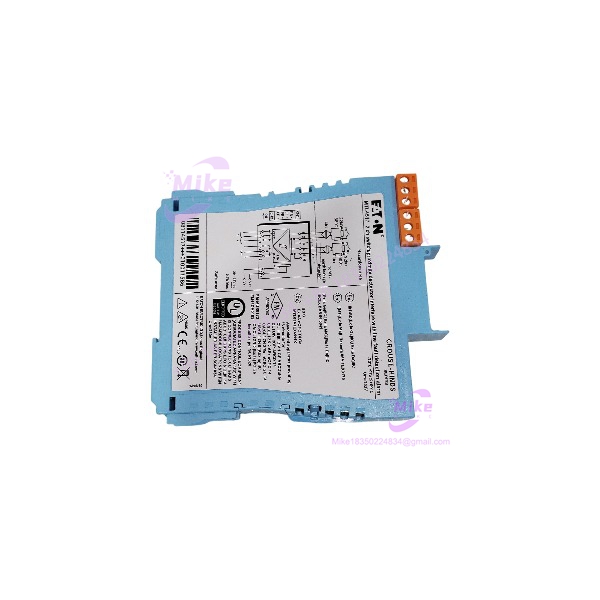
The MTL4517 serves as an intrinsically safe isolation barrier engineered for process control environments where discrete field signals must cross the hazardous boundary line. Installed on a backplane or mounting base within a safe area cabinet, this dual-channel module accepts inputs from Zone 0 or Zone 1 proximity detectors and mechanical switches, translating them through galvanic isolation to drive safe-area control loops. Selecting the correct hardware model ensures compliance with hazardous area classifications while eliminating cumbersome safety earth setups and protecting downstream logic controllers from dangerous fault voltages.
Integrating this unit into legacy or greenfield safety architectures requires careful verification of backplane bus compatibility and loop power requirements. System engineers must configure the side-mounted switches to match specific line fault detection and phase reversal preferences before mounting the hardware onto the rack. Ignoring these physical switch configurations during deployment frequently leads to mismatched signal logic or unannounced communication timeouts across the safety instrumented system.
MTL4517
Key Technical Specifications
| Parameter | Specification |
| Number of Channels | Two channels |
| Location of Switch/Detector | Zone 0, IIC, T6 hazardous area |
| Voltage Applied to Sensor | 7 to 9 V DC from 1 kOhm |
| Safe-Area Output | Two single-pole relays with normally open contacts + dedicated line fault relay |
| Contact Rating (Safe Area) | 250 V AC, 2A, cos >0.7; 40 V DC, 2A resistive |
| Current Consumption | 35 mA at 24 V DC |
| Power Dissipation | 0.84 W at 24 V DC |
| Ambient Temperature Range | -20°C to +60°C |
| SIL Capability | SIL 2 capable per IEC 61508 |
| Mounting | MTL4500 backplane mounting |
Field Engineer’s Pitfall Guide
- WARNING: Line Fault Resistor Mismatch. When utilizing the line fault detection feature with standard mechanical dry contacts rather than NAMUR proximity sensors, you must install appropriate end-of-line resistors (typically 500 ohms to 1k ohm in series, 20k to 25k in parallel). I once watched a commissioning team spend an entire shift chasing phantom alarm states because they omitted the required balancing resistors on simple pushbuttons.
- WARNING: Backplane Insertion Force. Never force the module onto the backplane bus if alignment pins are slightly offset. Forcing the connector will bend delicate gold contact pins, ruining both the module and the backplane slot.
- WARNING: Reactive Load Suppression. Always install proper RC snubbers or flyback diodes across inductive safe-area loads driven by the relay outputs. Unsuppressed inductive kickback will pit and weld the relay contacts shut within months of continuous operation.
QA & Testing SOP
- Visual & Origin Verification: Inspect the molded enclosure for thermal stress or cracks, verify factory laser markings, and ensure gold-plated edge connector pins are completely free of oxidation.
- Backplane Bench Test: Seat the module onto a live test backplane powered by a regulated 24V DC supply to confirm clean power rail distribution and steady green status LED illumination.
- Input Simulation & Switching Test: Use a calibrator to inject precise currents (simulating NAMUR sensor states above 2.1mA and below 1.2mA) to verify channel output relay state transitions and response times.
- Line Fault Verification: Introduce open and short-circuit conditions on the input channel terminals to confirm proper activation of the dedicated line fault relay and warning indicators.
- Packaging: Enclose in static-shielding material and pack with dense anti-static foam inside a sturdy cardboard container.
Technical FAQ
Can I hot-swap this safety barrier while the process loop is powered?
Yes. The MTL4500 series design permits hot-swapping modules on powered backplanes without causing spurious trips, provided standard plant safety protocols for live maintenance are followed.
How do I enable or disable line fault detection on this specific model?
Line fault detection and phase reversal are controlled via physical slide switches located on the side of the housing, which must be set before snapping the unit onto the backplane.
Does this interface support functional safety applications up to SIL 3?
It is SIL 2 capable as a single device (HFT=0) and can achieve SIL 3 capability when utilized in hardware redundant safety configurations (HFT=1) according to IEC 61508 guidelines.
What is the maximum switching voltage permitted on the safe-area relay outputs?
The safe-area relay contacts are rated for up to 250V AC at 2A or 40V DC at 2A under resistive load conditions.





